Vehicular washer device

a technology of washer and washer body, which is applied in the direction of vehicle maintenance, vehicle cleaning, functional valve types, etc., can solve the problems of increasing manufacturing cost, increasing power consumption of vehicle electric heater, and complicated cooling water piping of engine, so as to achieve simplified vortex tube structure, the effect of avoiding increasing power consumption and complication of piping

Inactive Publication Date: 2018-09-20
HONDA MOTOR CO LTD
View PDF3 Cites 2 Cited by
  • Summary
  • Abstract
  • Description
  • Claims
  • Application Information

AI Technical Summary

Benefits of technology

[0006]An aspect of the present invention provides a vehicular washer device capable of spraying heated washer fluid to a cleaning target without causing an increase in power consumption or complication of piping.
[0009]According to the aspect (1), when the washer fluid flows into the vortex tube in the connection passage, the washer fluid is separated into the hot fluid and the cold fluid inside the vortex tube, and the washer fluid of the separated hot fluid is discharged from the spray nozzle onto the cleaning target. In the case of this vehicular washer device, since a part of the washer fluid can be turned into a hot fluid in the vortex tube without using electric heating, power consumption of the vehicle can be suppressed. Further, complication of piping as in a case in which engine cooling water is used is not caused.
[0010](2) In the aspect (1), a one-way valve that prevents backflow of the washer fluid from the spray nozzle side may be provided inside the vortex tube.
[0011]According to the aspect (2), since it is not necessary to provide the one-way outside valve separately from the vortex tube, the number of parts can be reduced and a structure of the connection passage can be simplified.
[0013]According to the aspect (3), since a high temperature side flow and a low temperature side flow inside the main passage can be separated by using the one-way valve, a structure of the vortex tube can be simplified.
[0014]According to the aspect of the present invention, since the vortex tube is interposed in the connection passage connecting the tank and the spray nozzle, and the washer fluid turning into the hot fluid in the vortex tube is discharged toward the spray nozzle, it is possible to discharge the heated washer fluid to the cleaning target without causing an increase in power consumption and complication of piping.

Problems solved by technology

However, when the washer fluid is heated by the electric heater, power consumption of the vehicle by the electric heater increases.
Further, when the washer fluid is heated by the heat of the engine cooling water, cooling water piping of an engine becomes complicated, which is likely to cause an increase in manufacturing cost.

Method used


Image

  • Vehicular washer device
  • Vehicular washer device
  • Vehicular washer device

Examples


Embodiment Construction

[0019]Hereinafter, an embodiment of the present invention will be described below with reference to the drawings.

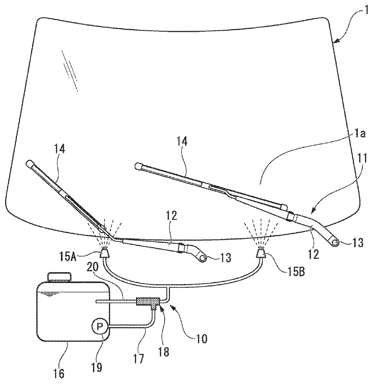
[0020]FIG. 1 is a front view of a portion of a windshield glass 1 on the front side of a vehicle that adopts a vehicular washer device 10 (hereinafter referred to as a “washer device 10”) according to an embodiment.

[0021]A pair of left and right wiper arms 12 of a wiper device 11 are installed at positions spaced to the left and right on a vehicle body panel under the windshield glass 1. A base portion of each wiper arm 12 is rotatably supported by a pivot shaft 13. A wiper blade 14 for wiping an outer surface 1a of the windshield glass 1 is held at an end portion of each wiper arm 12. In the embodiment, the windshield glass 1 is a cleaning target.

[0022]Further, a pair of left and right spray nozzles 15A and 15B of the washer device 10 are installed on the vehicle body panel under the windshield glass 1. The spray nozzles 15A and 15B are disposed at positions spaced to th...


PUM


Abstract

A vehicular washer device includes a tank that stores a washer fluid, a spray nozzle that sprays the washer fluid to a cleaning target, and a connection passage that connects the tank and the spray nozzles. A vortex tube that separates the washer fluid supplied from the tank into a hot fluid and a cold fluid and discharges the hot fluid toward the spray nozzles is interposed in the connection passage.

Description

CROSS-REFERENCE TO RELATED APPLICATION[0001]This application claims priority based on Japanese Patent Application No. 2017-053630 filed Mar. 17, 2017, the contents of which are incorporated herein by reference.BACKGROUND OF THE INVENTIONField of the Invention[0002]The present invention relates to a vehicular washer device that sprays a washer fluid to a cleaning target such as a windshield glass.Description of Related Art[0003]As a vehicular washer device, a vehicular washer device that heats a washer fluid with an electric heater or heat of engine cooling water and sprays the heated washer fluid to a cleaning target is known (for example, see Japanese Utility Model Publication No. Sho 62-32930 and Japanese Unexamined Patent Application, First Publication No. Sho 58-53549).SUMMARY OF THE INVENTION[0004]However, when the washer fluid is heated by the electric heater, power consumption of the vehicle by the electric heater increases.[0005]Further, when the washer fluid is heated by th...

Claims


Application Information

Patent Timeline
Patent Type & Authority Applications(United States)
IPC IPC(8): B60S1/48B60S1/52B60S1/50F16K15/02
CPCB60S1/487B60S1/52B60S1/50F16K15/026
Inventor HASHIMOTO, TAKUROSASAKI, TAKESHI
Owner HONDA MOTOR CO LTD
Why Eureka
Try Eureka