Variable filter circuit and wireless communication apparatus

a filter circuit and filter circuit technology, applied in the direction of electrical devices, multiple-port networks, capacitors, etc., can solve the problems of increasing the circuit size and complication of the control system, difficult to obtain steep filter circuit attenuation characteristics near the low-frequency side of the pass band, and difficult to obtain desired attenuation characteristics

Active Publication Date: 2017-10-10
MURATA MFG CO LTD
View PDF27 Cites 0 Cited by
  • Summary
  • Abstract
  • Description
  • Claims
  • Application Information

AI Technical Summary

Benefits of technology

[0008]Accordingly, the present disclosure provides a variable filter circuit and a wireless communication apparatus in which it is easy to obtain steep attenuation characteristics near a low-frequency side of a pass band and in which the circuit size is not easily increased and the control system is not easily complicated even when multiple stages are configured.
[0023]According to the present disclosure, steep attenuation characteristics can be achieved near a low-frequency side of a pass band, and a cutoff frequency on the low-frequency side of the pass band can be adjusted by controlling a variable reactance. As such, even in the case where a variable filter circuit is configured having n stages of serial arms, the number of variable reactances need only to be n+1, which makes it possible to suppress an increase in the circuit size and complication of the control system more than has been possible with conventional configurations.

Problems solved by technology

In a conventional variable filter circuit, although a pass band can be adjusted by controlling a variable capacitance, it has been difficult to obtain desired attenuation characteristics.
Specifically, it has been difficult to obtain steep attenuation characteristics near a low-frequency side of the pass band.
This has led to an increase in the circuit size and complication of the control system.

Method used


Image

  • Variable filter circuit and wireless communication apparatus
  • Variable filter circuit and wireless communication apparatus
  • Variable filter circuit and wireless communication apparatus

Examples


first embodiment

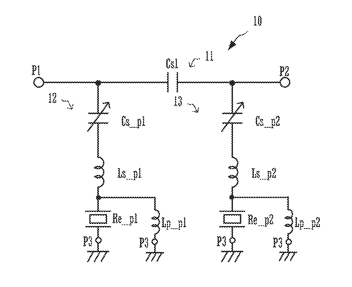
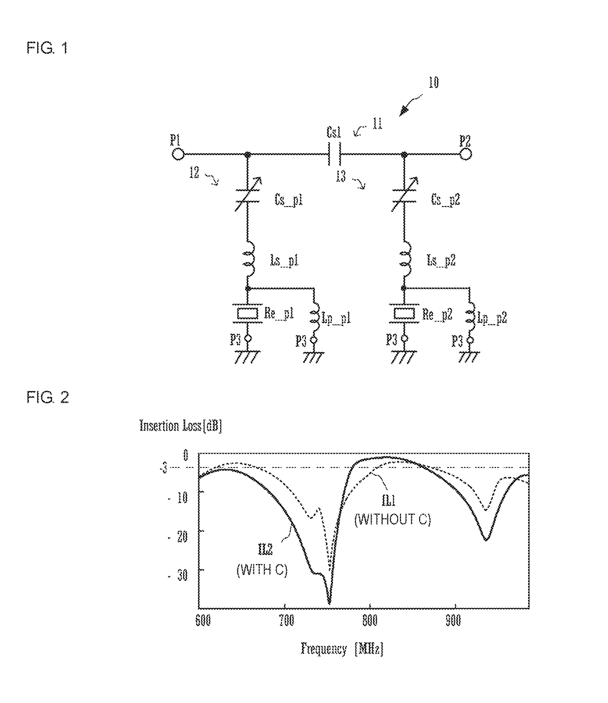
[0039]FIG. 1 is a circuit diagram illustrating a variable filter circuit 10 according to a first embodiment of the present disclosure.

[0040]The variable filter circuit 10 includes ports P1, P2, and P3, a serial arm 11, and parallel arms 12 and 13. The port P1 is a first input / output end of the variable filter circuit 10. The port P2 is a second input / output end of the variable filter circuit 10. The port P3 is a ground connection end of the variable filter circuit 10. The serial arm 11 is connected in series between the port P1 and the port P2. The parallel arm 12 is connected in series between the port P1 and the port P3. The parallel arm 13 is connected in series between the port P2 and the port P3.

[0041]The serial arm 11 includes a capacitor Cs1. The capacitor Cs1 is provided between the port P1 and the port P2, with one end thereof connected to one end of the parallel arm 12 and another end thereof connected to one end of the parallel arm 13.

[0042]The parallel arm 12 includes a ...

second embodiment

[0084]FIG. 9A is a circuit diagram illustrating a variable filter circuit 20 according to a second embodiment.

[0085]The variable filter circuit 20 includes a serial arm 21 and parallel arms 22 and 23. The parallel arm 22 includes the variable capacitance Cs_p1 and the resonator Re_p1. The parallel arm 23 includes the variable capacitance Cs_p2 and the resonator Re_p2. The resonator Re_p1 has a resonance point and an anti-resonance point further on the high-frequency side than the resonator Re_p2, and the resonator Re_p2 has a resonance point and an anti-resonance point further on the low-frequency side than the resonator Re_p1. In other words, of the parallel arms 22 and 23, the parallel arm 22 corresponds to a communication band further on the high-frequency side, and the parallel arm 23 corresponds to a communication band further on the low-frequency side. The element values of the variable capacitances Cs_p1 and Cs_p2 are controlled in order to appropriately adjust a cutoff frequ...

third embodiment

[0096]FIG. 11 is a circuit diagram illustrating a variable filter circuit 30 according to a third embodiment.

[0097]The variable filter circuit 30 includes a first circuit portion 30A and a second circuit portion 30B. The first circuit portion 30A and the second circuit portion 30B both have the same circuit configuration as the variable filter circuit 10 described earlier in the first embodiment. The first circuit portion 30A includes a serial arm 31 and parallel arms 32 and 33. The second circuit portion 30B includes a serial arm 34 and parallel arms 35 and 36.

[0098]Here, the parallel arm 32 includes the resonator Re_p1, the variable capacitance Cs_p1, the serial inductor Ls_p1, and the parallel inductor Lp_p1. The parallel arm 33 includes the resonator Re_p2, the variable capacitance Cs_p2, the serial inductor Ls_p2, and the parallel inductor Lp_p2. The parallel arm 35 includes a resonator Re_p3, the variable capacitance Cs_p3, a serial inductor Ls_p3, and a parallel inductor Lp_p...


PUM


Abstract

A variable filter circuit includes a serial arm connected between ports (P1-P2), a parallel arm having a resonator connected in series between ports (P1-P3), and another parallel arm having another resonator connected in series between ports (P2-P3). The serial arm includes a capacitor connected between the ports (P1-P2), and the parallel arms include variable capacitances connected in series to the resonators.

Description

[0001]This application is a continuation of International Application No. PCT / JP2015 / 053170 filed on Feb. 5, 2015 which claims priority from Japanese Patent Application No. JP2014-202072 filed on Sep. 30, 2014 and Japanese Patent Application No. JP2014-023342 filed on Feb. 10, 2014. The contents of these applications are incorporated herein by reference in their entireties.BACKGROUND[0002]Technical Field[0003]The present disclosure relates to a variable filter circuit and a wireless communication apparatus including the variable filter circuit.[0004]Background Art[0005]Conventional variable filter circuits have been given ladder configurations, in which basic circuits are configured by connecting variable capacitances in parallel or in series to resonators such as SAW resonators or BAW resonators and such basic circuits are then combined in multiple stages (see Patent Document 1, for example). In a variable filter circuit, an anti-resonant frequency of each basic circuit is adjusted...

Claims


Application Information

Patent Timeline
Patent Type & Authority Patents(United States)
IPC IPC(8): H04B1/10H03H9/54H03H7/075H03H9/60H03H7/01H03H9/64H01G17/00H04B1/00H04B1/12H01G7/06
CPCH03H7/0115H01G7/06H01G17/00H03H7/0153H03H7/075H03H9/605H03H9/6483H04B1/0064H04B1/126H03H9/542H03H2210/025
Inventor OGAMI, TAKASHITADA, HITOSHITANI, MASAKAZUSUGIYAMA, SHOUZO
Owner MURATA MFG CO LTD
Why Eureka
Try Eureka