Stacked Plate Heat Exchanger With Form Fitting Connection Of The Plates

a technology of heat exchanger and form fitting, which is applied in the direction of heat exchanger fastening, lighting and heating apparatus, climate sustainability, etc., can solve the problems of affecting the overall appearance of the device, affecting the sealing effect of the installation, and weakening the use effect of the device, so as to reduce the complexity of operation, ensure the connection, and ensure the effect of stability and reliability

Active Publication Date: 2018-09-20
ZEHNDER VERKAUFS UND VERW
View PDF2 Cites 8 Cited by
  • Summary
  • Abstract
  • Description
  • Claims
  • Application Information

AI Technical Summary

Benefits of technology

[0020]The heat exchanger according to the present invention puts the first heat exchange plate and the second heat exchange plate in interference connection through the engagement between the snap projection and the snap groove, which effectively ensures stability and reliability of the connection, ensures the airtightness of the connection, reduces the operating complexity due to sealing through a sealing glue or sealing strip according to the prior art, and avoids the situation in which the device appearance becomes unsightly due to the leakage of the sealing glue or movement of the sealing strip. In addition, the air inlet and the air outlet of the first heat exchange plate are set to be in different directions than those of the air inlet and the air outlet of the second heat exchange plate, which effectively ensures that the air of different qualities in different areas flows in different air channels, is healthy and environmentally friendly, effectively improves the practicability of the device, and is favorable for market promotion and applications.

Problems solved by technology

The present invention provides a heat exchanger, for solving the problem of the prior art that sealed connection is achieved through a bonding agent or sealing strip, leading to complex operations, and in the installation process, the sealing glue tends to leak or the sealing strip tends to move, making it impossible to ensure the sealing effect of the installation, consequently weakening the use effect of the device, affecting the overall appearance of the device, and making it unfavorable for market promotion and applications.

Method used


Image

  • Stacked Plate Heat Exchanger With Form Fitting Connection Of The Plates
  • Stacked Plate Heat Exchanger With Form Fitting Connection Of The Plates
  • Stacked Plate Heat Exchanger With Form Fitting Connection Of The Plates

Examples


Embodiment Construction

[0032]Specific implementation of the present invention will be further described in detail below with reference to the accompanying drawings and examples. The following examples are used to describe the present invention, not to limit the scope of the present invention.

[0033]In the present invention, terms, “first” and “second”, are only used for the purpose of description, which may not be construed as indication or implication of relative importance; terms like “installation” and “connection” shall be construed in a broad sense, unless otherwise specifically stipulated and defined, for example, “connection” may be a fixed connection, a removable connection, or an integral connection. To those skilled in the art, specific meanings of the above terms herein may be understood according to specific situations.

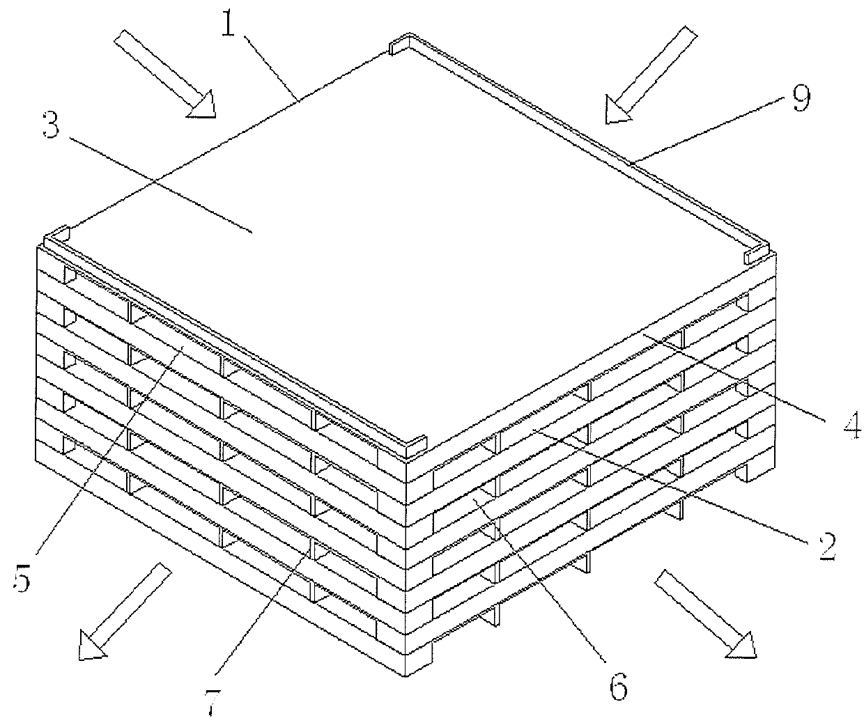
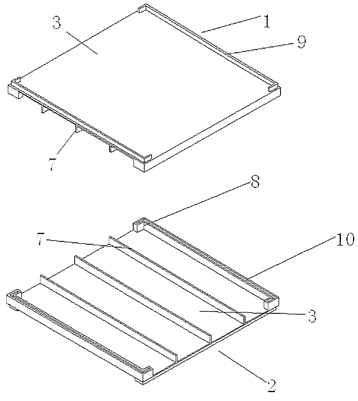
[0034]FIG. 1 is a schematic diagram of the structure of a heat exchanger; FIG. 2 is an exploded view of the structure of the connection between the first heat exchange plate and ...


PUM


Abstract

The present invention provides a heat exchanger, comprising a plurality of first heat exchange plates (1) and second heat exchange plates (2) that are connected sequentially and at an interval; the first heat exchange plates (1) and the second heat exchange plates (2) each comprise a heat exchange sheet (3) and a heat exchange frame (4) disposed on side ends of the heat exchange sheet (3); the side ends of the heat exchange sheet (3) are formed with a snap projection (9) in a direction away from the heat exchange frame (4); the heat exchange frame (4) is formed with a snap groove (10); the first heat exchange plates (1) and the second heat exchange plates (2) are in interference connection through the engagement between the snap projection (9) and the snap groove (10); an air channel (5, 6) is formed between a first heat exchange plate (1) and an adjacent second heat exchange plate (2), the air inlet of the first heat exchange plate (1) and the air inlet of the second heat exchange plate (2) have different directions, and the air outlet of the first heat exchange plate (1) and the air outlet of the second heat exchange plate (2) have different directions. The present invention puts the first heat exchange plate (1) and the second heat exchange plate (2) in interference connection through the engagement between the snap projection (9) and the snap groove (10), which effectively ensures stability and reliability of the connection, and ensures the airtightness of the connection.

Description

FIELD OF THE INVENTION[0001]The present invention relates to a heat exchanger, and in particular to a heat exchanger for gases.DESCRIPTION OF THE RELATED ART[0002]As energy-saving and emission-reduction policies are implemented, buildings have better and better airtightness, and indoor ventilation has become a necessary condition; to save energy and provide comfort, ventilation devices with heat recovery and purification capabilities are very popular on the market.[0003]Existing heat exchangers comprise a plurality of heat exchange units, and heat exchange units are in sealed connection with each other through a bonding agent or sealing strip to form a set of air channels in the same fixed direction.[0004]In the process of implementing the technical solution according to the present invention, however, the inventor found that the existing heat exchanger installation structure performs sealed connection through a bonding agent or sealing strip, leading to complex operations, and in t...

Claims


Application Information

Patent Timeline
Patent Type & Authority Applications(United States)
IPC IPC(8): F28F3/10F28D9/00
CPCF28F3/10F28D9/0037F28F2250/106F28F2275/14F28F2275/085F28F2275/08F28D9/0062F28D9/0068Y02B30/56
Inventor GUO, ZHANGENGRAN, HONGWEI
Owner ZEHNDER VERKAUFS UND VERW
Why Eureka
Try Eureka