Lunar phase display device

a display device and phase technology, applied in the field of linear phase display devices, can solve the problems of complex and large thickness

Active Publication Date: 2018-09-20
BLANCPAIN SA
View PDF0 Cites 0 Cited by
  • Summary
  • Abstract
  • Description
  • Claims
  • Application Information

AI Technical Summary

Benefits of technology

[0013]The display device according to the first aspect of the invention may also exhibit one or

Problems solved by technology

However, they are complica

Method used


Image

  • Lunar phase display device
  • Lunar phase display device

Examples


Embodiment Construction

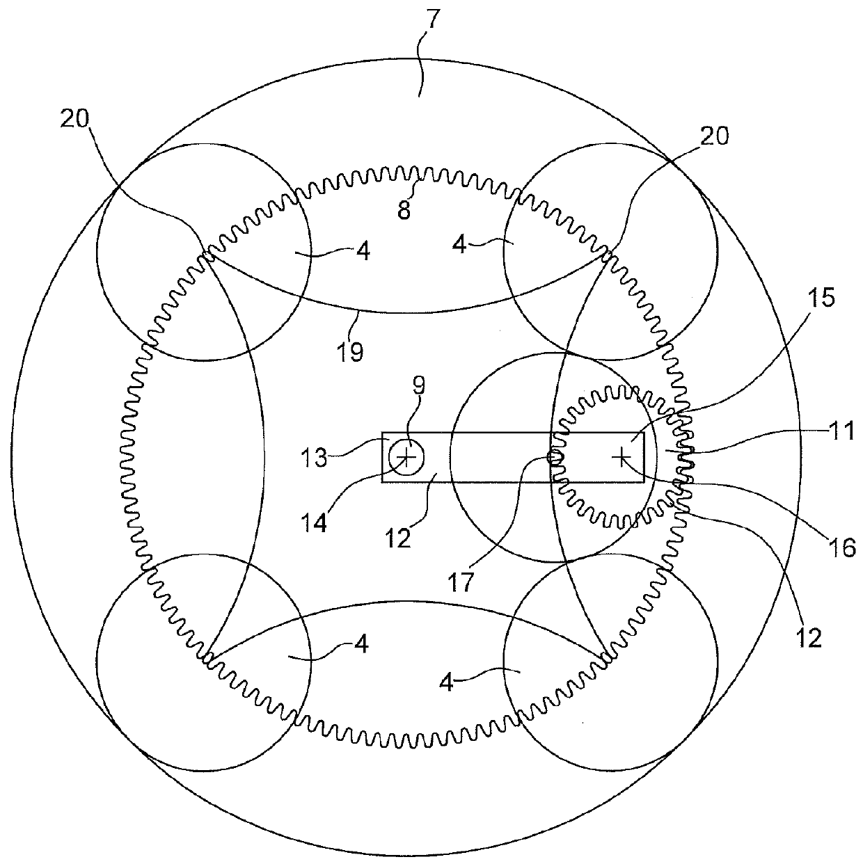
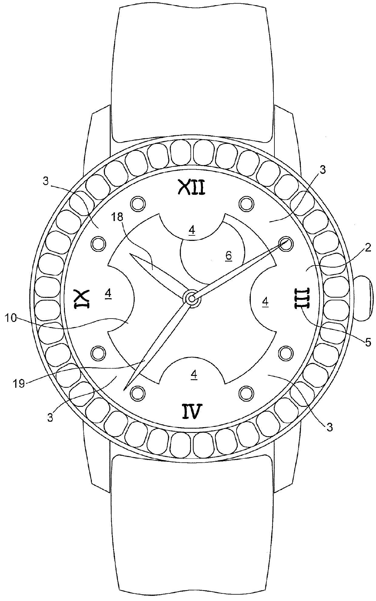
[0033]A display device 1 and a watch including such a display device will now be described with reference to FIGS. 1 and 2.

[0034]Display device 1 includes a cover 2. This cover 2 is annular. Annular cover 2 has a symmetry of revolution with respect to its centre 9. Cover 2 includes four ring portions 3. Two successive ring portions 3 are separated by a convex lobe 4 protruding radially towards the inside of cover 2. Lobes 4 are preferably evenly distributed over the periphery of cover 2, such that ring portions 3 all have the same length.

[0035]Cover 2 preferably forms the dial of a watch as represented in FIG. 2. Lobes 4 are preferably arranged at 3 o'clock, 6 o'clock, 9 o'clock and 12 o'clock.

[0036]Cover 2 preferably includes symbols 5. Each symbol 5 is preferably aligned with a lobe 4 as represented in FIG. 2.

[0037]The display device also includes a disc 6 representing the moon. This disc 6 is also called the “moon indicator disc” in this document. This disc 6 can represent the mo...


PUM


Abstract

A lunar phase display device including an annular cover including four ring portions, two successive ring portions being separated by a convex lobe projecting radially towards the inside of the annular cover; a moon indicator disc, a drive device arranged to move the moon indicator disc so that the disc makes a cycloidal trajectory between two successive lobes, the moon indicator disc being at least partially occulted by each of the two lobes during one portion of the cycloidal trajectory so as to reproduce the phases of the moon during a lunar month.

Description

[0001]This application claims priority from European Patent Application No. 17161916.6 filed on Mar. 20, 2017, the entire disclosure of which is hereby incorporated herein by reference.FIELD OF THE INVENTION[0002]The invention relates to a device for the display of the current lunar phase visible at a determined point on the earth's surface.BACKGROUND OF THE INVENTION[0003]In the prior art there are numerous lunar phase display devices, especially incorporated in watches.[0004]By way of example, EP Patent No 2392976 discloses a device comprising a moon disc and a dial comprising an aperture of substantially semi-circular shape. The moon disc is driven in rotation to display the indications marked on the moon disc through the aperture to indicate the phases of the moon. This mechanism includes a first occultation disc rotatably housed between the moon disc and the dial, and a drive train driving the first occultation disc such that the indications marked on the moon disc are at least...

Claims


Application Information

Patent Timeline
IPC IPC(8): G04B19/26G04B19/04
CPCG04B19/268G04B19/046G04B13/02G04B19/26
Inventor ROBIN, MARTIN
Owner BLANCPAIN SA
Why Eureka
Try Eureka