Connector assembly and connector cover

a technology of connectors and connector parts, applied in the direction of coupling bases/cases, coupling device connections, electrical devices, etc., can solve the problems of cover deformation and cover disengagement from the connector, and achieve the effect of preventing the disengagement of the cover, preventing the curvature of the cover caused by being struck by a water flow, and preventing the cover from disengaging from the connector

Active Publication Date: 2018-09-20
MOLEX INC
View PDF8 Cites 6 Cited by
  • Summary
  • Abstract
  • Description
  • Claims
  • Application Information

AI Technical Summary

Benefits of technology

[0006]An object of the present disclosure is to provide a connector assembly and a connector cover that prevent disengagement of a cover caused by an external force acting thereon such as being struck by a water flow.
[0007]A connector assembly according to the present disclosure may have a connector having a terminal installed to a tip of a cable and a housing having a terminal housing portion, which includes a through hole that houses the terminal and an opening where through a terminal of another connector is inserted, and a lead-out portion, which includes a through hole where through the cable is inserted and an opening that lead out the cable; and a cover installed to the connector for curving the cable, which extends along a first direction that is a lead-out direction of the cable from the lead-out portion, in a direction different from the first direction. Here, the cover may have a hood portion that covers the lead-out portion and a slit that is formed in the hood portion and where through the curved cable is inserted. Moreover, the housing may have an outer shell portion that is disposed on an outer side of the hood portion of the cover and covers at least a portion of the hood portion. By this, curving of the cover caused by being struck by a water flow can be prevented and the cover disengaging from the connector can be prevented.

Problems solved by technology

This results in the cover deforming and the engaging hole of the cover disengaging from the engaging claw of the connector, and there is a possibility that the cover will disengage from the connector.

Method used


Image

  • Connector assembly and connector cover
  • Connector assembly and connector cover
  • Connector assembly and connector cover

Examples


Embodiment Construction

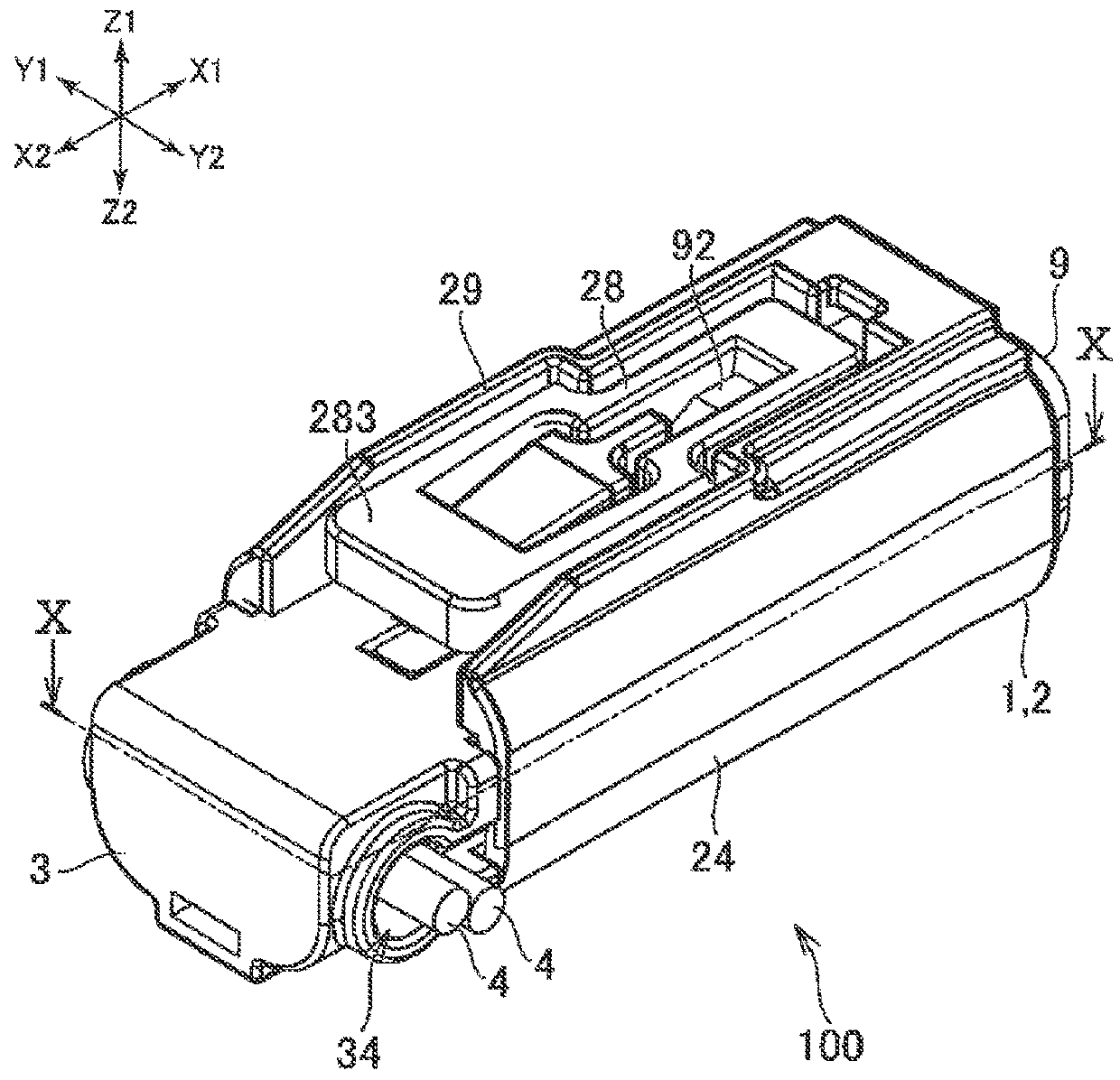
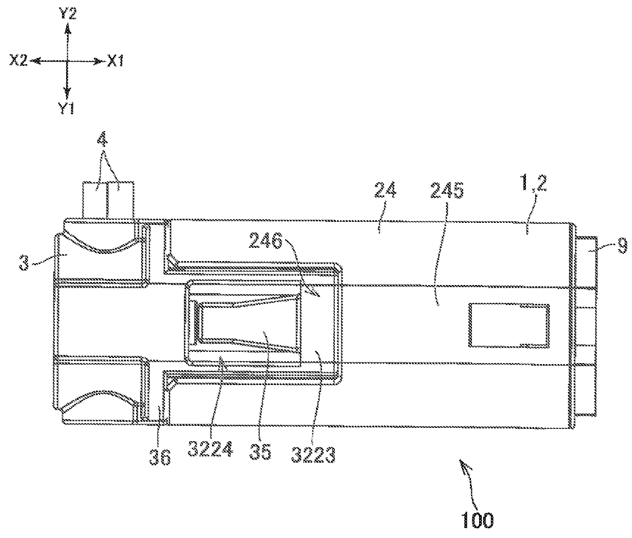
[0030]In the present embodiment, a direction wherein a connector 1 is inserted into another connector 9 (direction indicated by X1 in each diagram) is defined as frontward and a direction wherein the connector 1 is removed from the other connector 9 (direction indicated by X2 in each diagram) is defined as rearward. Moreover, among directions indicating a width of the connector 1, one (direction indicated by Y1 in each diagram) is defined as leftward and another (direction indicated by Y2 in each diagram) is defined as rightward. Moreover, among directions indicating a height of the connector 1, one (direction indicated by Z1 in each diagram) is defined as upward and another (direction indicated by Z2 in each diagram) is defined as downward. Note that the various directions are only for describing relative positional relationships of parts configuring the connector 1 and do not indicate absolute directions.

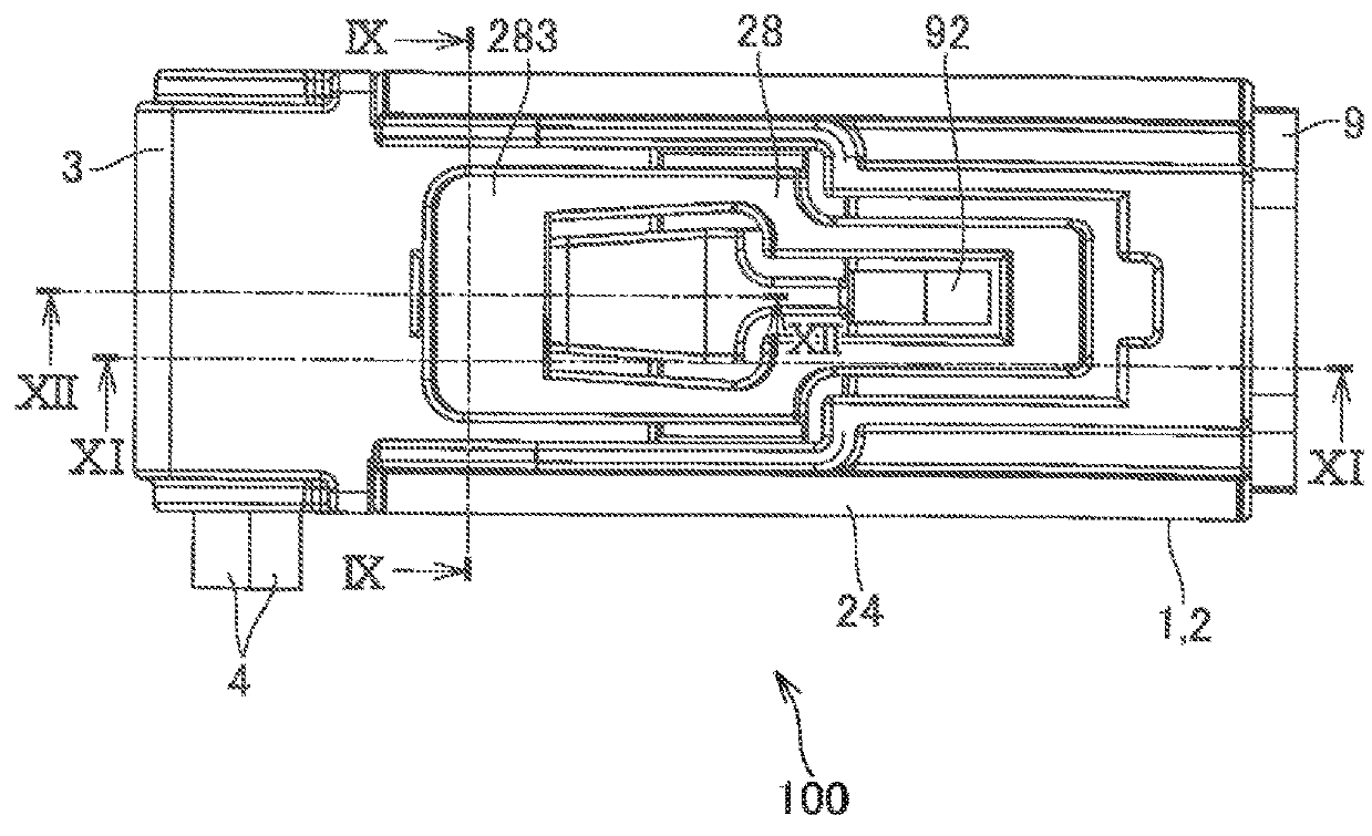
[0031]As illustrated in FIG. 1 and FIG. 4, a connector assembly 100 according...


PUM


Abstract

A connector assembly may have a cover installed to a connector for curving a cable extending from a lead-out portion of a housing in a direction different from a lead-out direction of the cable. The cover may have a hood portion that covers the lead-out portion of the housing and a slit that is formed in the hood portion and where through the cable is inserted. The housing may have an outer shell portion that is disposed on an outer side of the hood portion of the cover and covers at least a portion of the hood portion.

Description

RELATED APPLICATIONS[0001]This application claims priority to Japanese Application No. 2017-051878, filed Mar. 16, 2017, which is incorporated herein by reference in its entirety.TECHNICAL FIELD[0002]The present disclosure relates to a connector assembly and a connector cover.BACKGROUND ART[0003]Patent document 1 below discloses a cover (electrical-wire cover 50 in patent document 1) installed to a connector (connector housing 10). An engaging hole is formed in the cover. An engaging claw of the connector protruding from an inner side of the cover is caught by an edge of this engaging hole. By this, the cover is prevented from falling off of the connector.[0004]Patent Document 1: JP 2002-054206 ASUMMARY[0005]In patent document 1, in a state where the cover is covering the connector, an outer face of the cover covering the connector is exposed to an outer side of the connector. Here, when a product installed with the connector is washed with water or the like, a water flow comes to d...

Claims


Application Information

Patent Timeline
Patent Type & Authority Applications(United States)
IPC IPC(8): H01R13/52H01R13/502
CPCH01R13/5213H01R13/502H01R13/5219H01R13/426H01R13/5025H01R13/4367H01R13/506H01R13/5205H01R13/5841
Inventor OKAMURA, JUNPEIHANYU, TAKUJI
Owner MOLEX INC
Why Eureka
Try Eureka