Overturn preventing device

a technology of preventing device and turning, which is applied in the direction of shock absorbers, furniture parts, mechanical apparatuses, etc., can solve the problems of difficult mounting overturn work, and achieve the effect of confirming work becoming more accurate and easy to us

Inactive Publication Date: 2018-09-27
KYB CORP
View PDF0 Cites 2 Cited by
  • Summary
  • Abstract
  • Description
  • Claims
  • Application Information

AI Technical Summary

Benefits of technology

[0019]In the fixing cord of the overturn preventing device of the invention, the location of the first mark may be a cutting location. According to the construction, the cutting location can clearly be presented to the worker carrying out the mounting work. And, in the mounted state after the cutting, it can be confirmed whether or not the length of the damper is below a predetermined maximum length by confirming the positional relationship between the lower end of the fixing cord drooping from the base abutting against the ceiling and the predetermined part of the damper. As a result, the confirming work becomes more accurate and easier.
[0020]The fixing cord of the overturn preventing device may have through hole parts respectively formed at a location near one of the bases and at a location near the other base. In the case of mounting this overturn preventing device, the overturn preventing device is placed on the top surface of the article when being set in the contracted state by the fixing cord, and then the fixing code between the hole parts is loosened or cut, whereby the overturn preventing device can easily be mounted between the ceiling and the article. When the damper needs to be held in the contracted state again after the damper has been released from the contracted state by the fixing cord thereby to be caused to extend, the damper can be maintained in the contracted state again by connecting both hole parts using a wire, string or another connecting member.

Problems solved by technology

However, when the overturn preventing device of Patent.
Thus, there is a difficulty in the work of mounting overturn preventing device into the desired posture while the worker contracts the damper above the furniture.

Method used


Image

  • Overturn preventing device
  • Overturn preventing device
  • Overturn preventing device

Examples


first embodiment

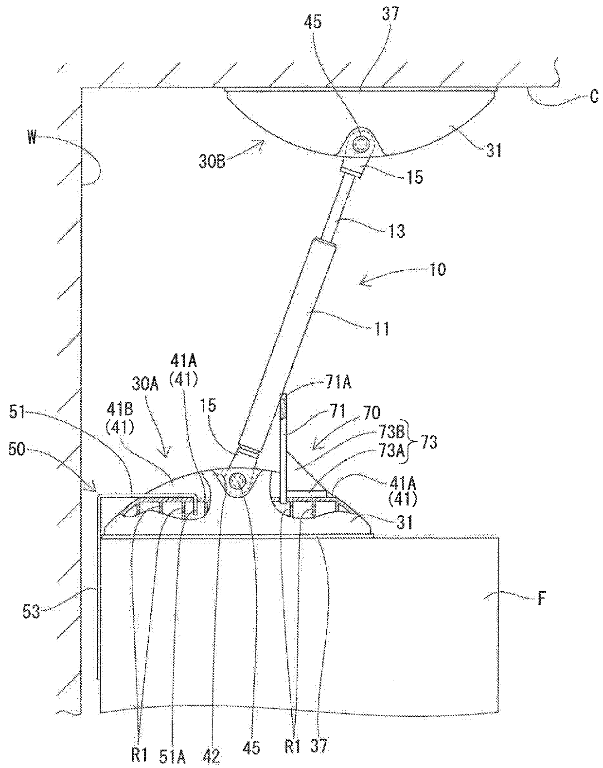
[0054]At least one overturn preventing device of the first embodiment is mounted between a top surface of a piece of furniture F and a ceiling C, as illustrated in FIG. 1. The furniture F is installed on a floor surface (not illustrated) while a rear surface of the furniture F is opposed to a wall surface W extending in a vertical direction from the floor surface. The furniture F is formed into a rectangular parallelepiped shape and has a door, drawers (neither illustrated) and the like in a front surface (a right side as viewed in FIG. 1), so that clothes, accessories and the like can be housed in the furniture F. The furniture F has a rectangle-shaped horizontal section long in a right-left direction (a depthwise direction in FIG. 1). When the overturn preventing device is not mounted on the furniture F, the furniture F would possibly be tilted frontward (rightward in FIG. 1) by shaking of earthquake or the like thereby to be overturned.

[0055]The overturn preventing device include...

second embodiment

[0102]A second embodiment will be described with reference to FIGS. 10 to 13 and the like.

[0103]The overturn preventing device 201 of the second embodiment as illustrated in FIG. 10 and the like differs from that of the first embodiment in that the fixing cord 90 (FIG. 7 and the like) has been changed to a fixing cord 290 as illustrated in FIG. 10 and the like. Other construction is same as that of the first embodiment and has the same function. Accordingly, except for the fixing cord 290, identical or similar parts are labeled by the same reference symbols as those in the first embodiment, and the detailed description of these parts will be eliminated. Although the furniture F installed on the installation surface is also exemplified as the article in the following description, the overturn preventing device may be applied to an article other than the furniture.

[0104]The overturn preventing device 201 as illustrated in FIG. 10 includes the damper 10 and the paired bases 30A and 30B...

third embodiment

[0118]A third embodiment will be described with reference to FIGS. 14 to 18 and the like.

[0119]The overturn preventing device 301 of the third embodiment as illustrated in FIG. 14 and the like differs from that of the first embodiment in that the fixing cord 90 (FIG. 7 and the like) has been changed to a fixing cord 390 as illustrated in FIGS. 14, 15 and the like. Other construction is same as that of the first embodiment and has the same function. Accordingly, except for the fixing cord 390, identical or similar parts are labeled by the same reference symbols as those in the first embodiment, and the detailed description of these parts will be eliminated. Although the furniture F installed on the installation surface is also exemplified as the article in the following description, the overturn preventing device may also be applied to an article other than the furniture.

[0120]The overturn preventing device 301 as illustrated in FIG. 14 includes the damper 10 and the paired bases 30A...


PUM


Abstract

Providing an overturn preventing device which can easily be mounted between a top surface of an article and a ceiling. The overturn preventing device includes a damper, a pair of bases and a fixing cord. The damper is mounted between a top surface of a piece of furniture installed on a floor and a ceiling. The bases are respectively coupled to both ends of the damper. The first base abuts against the top surface of the furniture, and the other base abuts against the ceiling. The fixing cord holds the damper in a contracted state in which the damper has a desired length.

Description

TECHNICAL FIELD[0001]The present invention relates to an overturn preventing device.BACKGROUND ART[0002]Patent Document 1 discloses a conventional overturn preventing device. This overturn preventing device includes a damper and a pair of bases. The damper is mounted between a top surface of a piece of furniture installed on a floor and a ceiling. The damper has two ends respectively supported by the paired bases to be rotatable about rotation axes. One of the bases abuts against the top surface of the furniture and the other s abuts against the ceiling. As a result, in this overturn preventing device, when the furniture is tilted by shaking of earthquake or the like in a direction parallel to a rotation direction of the damper, the damper is rotated about the rotation axes relative to the bases so that the bases can be maintained in abutment against the top surface of the furniture and the ceiling respectively. As a result, this overturn preventing device can apply a damping force ...

Claims


Application Information

Patent Timeline
Patent Type & Authority Applications(United States)
IPC IPC(8): A47B97/00
CPCA47B97/00A47B2097/008F16F9/061F16F15/023F16F9/54
Inventor ISHIHARA, YUKIKOOTA, AKIHISAIIDA, CHIKAUNE, MASAYA
Owner KYB CORP
Why Eureka
Try Eureka