Modular humeral head

a humeral head and module technology, applied in the field of humeral head assemblies and components, can solve problems such as restricting the motion of the shoulder joint, and achieve the effect of greater flexibility in placemen

Active Publication Date: 2018-10-04
HOWMEDICA OSTEONICS CORP
View PDF3 Cites 25 Cited by
  • Summary
  • Abstract
  • Description
  • Claims
  • Application Information

AI Technical Summary

Benefits of technology

[0006]There is a need for greater flexibility in placement of a humeral head relative to a humeral anchor for a shoulder joint. There is a need for humeral head assemblies that allow for an articular surface of the head to be either centered on or eccentric from an axis along which the humeral head is coupled with a humeral anchor. There is a need for humeral head assemblies that provide for a range of eccentricity to an assembly axis so that a wide range of patient needs can be met by the assembly.
[0009]The coupler can also include a collar disposed between the first portion and the second portion thereof, the collar including a protrusion configured to be positionable at least along the continuous zone of eccentricity adjustment. In some examples, the coupling portion includes a radial notch configured to receive the protrusion. Relative rotation of the coupler to the articular body is prevented when the protrusion is received in the notch. The position of the protrusion and the notch can be reversed, such that the coupling portion includes one or a plurality of protrusions at the discrete position site(s) and the collar includes a notch configured to receive a protrusion. In some embodiments, the radial notch is disposed circumferentially adjacent to the continuous zone of eccentricity adjustment. In other embodiments, the radial notch is disposed at a position where no eccentricity is provided between the coupler and the articular body when the protrusion is disposed in the notch.

Problems solved by technology

Joint conditions can develop that cause pain and restrict motion of the shoulder joint.

Method used


Image

  • Modular humeral head
  • Modular humeral head
  • Modular humeral head

Examples


Embodiment Construction

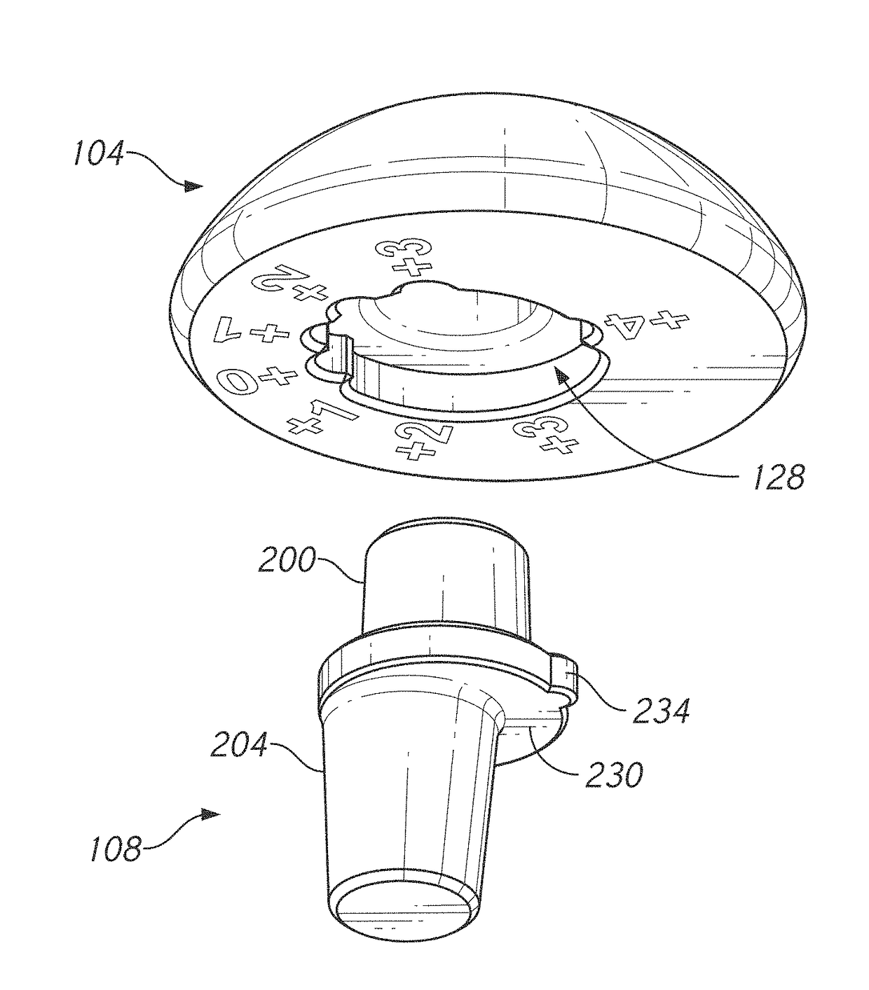
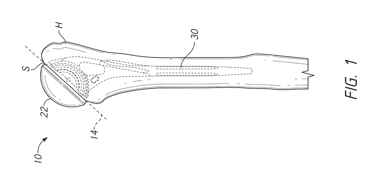
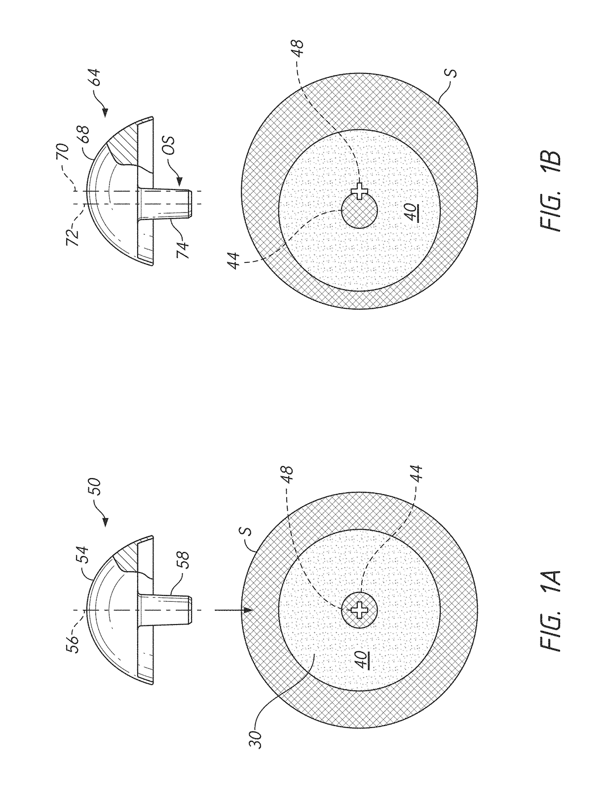
[0045]This application is directed to orthopedic assemblies that enable a first portion thereof to be selectively coupled with a second portion to selectively position the first portion aligned with or eccentric to the second portion. The first portion can be co-linear with the second portion. In applications discussed in detail below, the first portion can include an articular body and the second portion can include a bone anchor portion to be coupled to a bone. For example in the context of the shoulder, a humeral head assembly can be provided that enables an articular surface or other aspect of an articular body to be coupled with a humeral anchor in a centered position or in an eccentric position. In some variations, a glenoid anchor could be provided and a shoulder assembly could enable an articular body such as a glenosphere of a reverse shoulder implant to be disposed in a centered or eccentric position relative to the anchor. In further variations, an assembly can be adapted...


PUM


Abstract

A humeral head assembly is provided that includes an articular body and a coupler. The articular body includes a coupling portion disposed on a side of the articular body opposite an articular surface. The coupling portion includes a continuous zone of eccentricity adjustment. The coupler portion optionally includes one or more than one discrete position site. The coupler includes a first portion and a second portion opposite the first portion. The first portion is configured to mate with the coupling portion and the second portion is configured to mate with another member of a joint prosthesis. A coupling portion with the continuous range of eccentricity adjustment can be provided on a bone anchor and the eccentricity of another component can be selected by motion of a coupler, such as a tray for reverse humeral assemblies, along the coupling portion of the anchor.

Description

INCORPORATION BY REFERENCE TO ANY PRIORITY APPLICATIONS[0001]Any and all applications for which a foreign or domestic priority claim is identified in the Application Data Sheet as filed with the present application are hereby incorporated by reference under 37 C.F.R. § 1.57.BACKGROUNDField[0002]The present disclosure relates to humeral head assemblies and components thereof as well as methods for assembling and implanting them.Description of the Related Art[0003]Skeletal joints have a variety of configurations providing for a wide range of smooth movement of two or more bones relative to each other. For example, in a shoulder joint, an articulating surface at one end of the humerus interacts with an articulating surface at the glenoid cavity of the scapula in a manner similar to a “ball and socket” joint. Joint conditions can develop that cause pain and restrict motion of the shoulder joint. Implanting prosthetic components at one or both articulating surface of the joint can improv...

Claims


Application Information

Patent Timeline
Patent Type & Authority Applications(United States)
IPC IPC(8): A61F2/40
CPCA61F2/4014A61F2002/30354A61F2002/3054A61F2002/30714A61F2/30749A61F2/3859A61F2002/3069A61F2002/4022A61F2002/4051A61F2002/30329A61F2002/30332A61F2002/30403A61F2002/30604A61F2002/30617A61F2002/4018A61F2002/4029A61F2002/4044A61F2002/4037A61F2002/3071
Inventor MUTCHLER, AUSTIN WYATTKNOX, KEVIN P.
Owner HOWMEDICA OSTEONICS CORP
Why Eureka
Try Eureka