

Image forming apparatus
- Summary
- Abstract
- Description
- Claims
- Application Information
AI Technical Summary
Benefits of technology
Problems solved by technology
Method used
Image

Examples
Embodiment Construction
[0015]Hereinafter, an embodiment of the present disclosure will be described with reference to the accompanying drawings.
[0016]
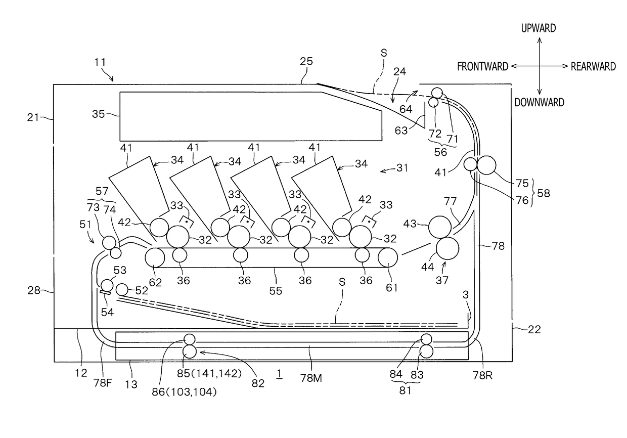
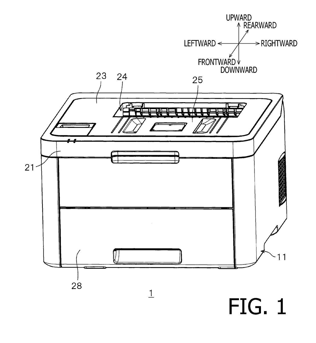
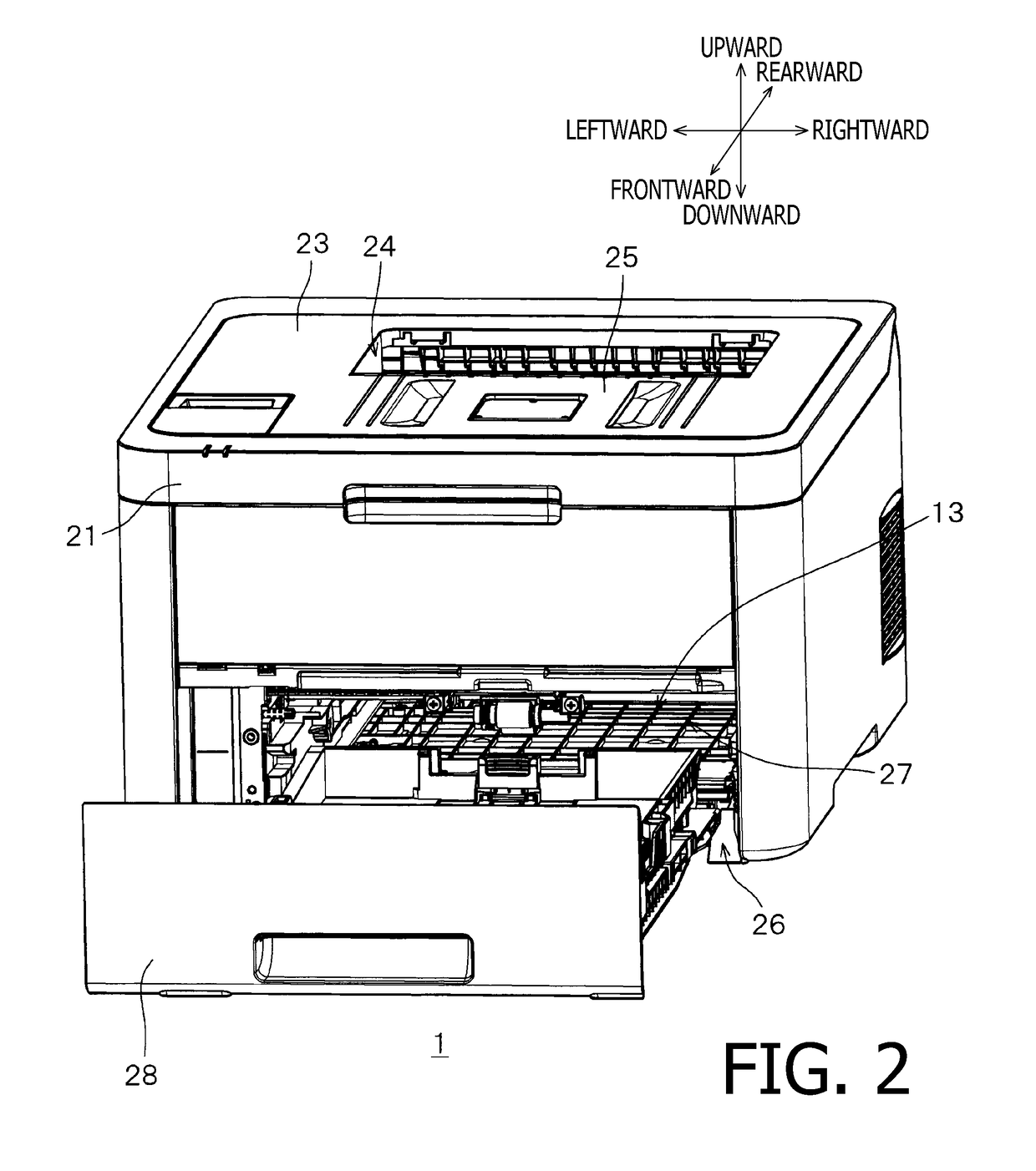
[0017]A printer 1, as shown in FIGS. 1-2, includes a body 11, a feeder tray 12, and a duplex conveyer 13.
[0018]The body 11 has a first side surface 21 and a second side surface 22 (see FIG. 4), which face each other at spaced apart positions. When the printer 1 is placed on a horizontal plane, the first side surface 21 and the second side surface 22 may stand substantially vertically to the horizontal plane. The body 11 includes an upper surface 23, which spreads between upper ends of the first side surface 21 and the second side surface 22. The upper surface 23 includes a dent 24, which dents downward. An area inside the dent 24 and an area closer to the first side surface 21 on the upper surface 23 form an ejection tray 25.
[0019]In the following description, directions related the printer 1 and each part or item included in the printer 1 will be mentioned ...
PUM
 Abstract
Description
Claims
Application Information