Non invasive process for the evaluation of the quality of internal dense connective tissues

Pending Publication Date: 2021-02-11
ECOLE CENT DE LYON +2
0 Cites 0 Cited by

AI-Extracted Technical Summary

Problems solved by technology

However, when it comes to internal organs, it might be difficult to obtain informations on the quality and function of an internal organ without obtaining and analyzing a sample of the tissue.
As human beings age, the structure of bone changes and they become less dense, and therefore weaker, placing elderly people at risk of breaks from a sudden bump or fall.
However, radiography is relatively insensitive to detection of early disease and requires a substantial amount of...

Benefits of technology

[0046]a cutaneous replica of stage 2 being indicative of low quality...

Abstract

The invention relates to a non-invasive process for evaluating the quality of one or more dense connective tissue(s) in a patient, comprising the following steps: a) Analyzing the profile of the microrelief of a cutaneous replica of a portion of the skin of said patient by at least one of the following step: a1. visually assessing on picture(s) of said cutaneous replica the line shape and the anisotropy of the lines; and/or a2. Determining, on picture(s) of said cutaneous replica, the roughness index of the microrelief with an optical sensor, b) identifying cutaneous replica of “stage 1”, representative of healthy skins, and cutaneous replica of “stage 2” representative of altered skins, a cutaneous replica of stage 2 being indicative of low quality of the one or more dense connective tissue(s) in the patients body.

Application Domain

Image enhancementImage analysis +3

Technology Topic

Dense connective tissueNon invasive +5

Image

  • Non invasive process for the evaluation of the quality of internal dense connective tissues
  • Non invasive process for the evaluation of the quality of internal dense connective tissues
  • Non invasive process for the evaluation of the quality of internal dense connective tissues

Examples

  • Experimental program(4)

Example

[0180]Based on the results presented in example 3, it has been concluded that: [0181] a cutaneous replica of stage 1 is defined as having a medium SILT value, comprised between 45 μm and 120 μm, the limits 45 and 120 μm being comprised into this range; and [0182] a cutaneous replica of stage 2 is defined as having an extreme SILT value, strictly inferior to 45 μm or strictly superior to 120 μm.
[0183]Step (b): Identifying Cutaneous Replica of “Stage 1” or “Stage 2”
[0184]According to the process of the invention, each cutaneous replica will be identified as being of “stage 1” or “stage 2”.
[0185]In a first embodiment of the invention, the step (al) comprising visually assessing parameters of the lines on the cutaneous replica is performed to identify stage 1 and stage 2 replicas.
[0186]In a specific embodiment of the invention, the process for evaluating the quality of a dense connective tissue in a patient consists in both steps (a1) and (b).
[0187]In a second embodiment of the invention, the step (a2) comprising determining the roughness index of the microrelief of the replica with an optical sensor is performed to identify stage 1 and stage 2 replicas.
[0188]In a specific embodiment of the invention, the process for evaluating the quality of a dense connective tissue in a patient consists in both steps (a2) and (b).
[0189]In these embodiments, steps a1 and a2 are implemented independently one of the other.
[0190]In a third embodiment of the invention, both steps (a1) and (a2) are performed successively to identify stage 1 and stage 2 replicas. In this case, if results are divergent, the result of step (a2) is considered to be the most reliable and therefore the discrimination between two stages is based on the result obtained with the step (a2).
[0191]In another specific embodiment of the invention, the process for evaluating the quality of a dense connective tissue in a patient consists in three steps (a1), (a2) and (b).
[0192]Cutaneous replicas of “stage 1” are representative of healthy skins, although cutaneous replicas of “stage 2” are representative of altered skins.
[0193]In the sense of the invention, an altered skin presents signs of ageing, with short, discontinuous lines, mainly oriented in the same direction. It is understood that the “skin ageing” phenomena is not directly dependent of the actual age of the individual, but depends also on external factors such as the rate of UV radiations the portion of skin has received, the use of protective creams or not, the intrinsic quality of the skin, the quality of the alimentation, the lifestyle of the individual, etc.
[0194]As shown in the examples section, inventors have identified a correlation between the stage of the cutaneous replica and (i) the quality of the bone and (ii) the quality of the dermis, and more generally a correlation between the stage of the cutaneous replica and the quality of any internal dense connective tissue of an individual.
[0195]In particular, results show that a cutaneous replica of stage 2 is indicative of low quality of one or more of the dense connective tissues in a patient's body.
[0196]Uses of the Non-Invasive Process According to the Invention
[0197]The process according to the invention can be used for several applications for various types of patients.
[0198]In particular, when the dense connective tissue whose quality is evaluated is bone, the process may be used for determining the risk of occurrence of a contralateral hip fracture in a patient.
[0199]In the sense of the invention, a contralateral hip fracture designates a second hip fracture occurring in a patient who had previously undergone a hip fracture of the other leg. It has been shown that the absolute risk of a contralateral hip fracture, after a first hip fracture, is 13.8% (Vochteloo et al., 2012). This risk concerns mainly the elderly persons, the age being a risk factor for a contralateral hip fracture.
[0200]The implementation of the process according to the invention would help to determine, among the patients having undergone a first hip fracture, those most at risk for suffering of a contralateral fracture. By determining the stage of their cutaneous replica, it would be possible to discriminate the patients who would need a close follow-up, and those who would not necessitate this follow-up.
[0201]More generally, the non-invasive process according to the invention is useful for evaluating a risk of the occurrence of a future fracture. This information is useful to the patient, who may adapt his or her lifestyle, but also to the physician and/or clinician in determining the most effective course of treatment.
[0202]This determination of the quality of a dense connective tissue will assist the physician and/or clinician in his choice of preventive and/or therapeutic approach for each patient, in a personalized manner.
[0203]In another embodiment of the invention, the process is used for following over time the quality of one or more dense connective tissues in a patient.
[0204]In particular in an elderly person, it might be useful to follow over time the quality of the dense connective tissue, in particular of the bones of the patient, in order to adapt his/her lifestyle and in particular his/her level of physic activity.
[0205]When the quality of dermis is estimated, the process may be used for determining the risk of occurrence of skin disorders in said individual, and might be useful to adapt the hygienic routine of the individual.
[0206]Kit Useful for Performing the Process of the Invention
[0207]The invention is also directed to a diagnostic kit comprising: [0208] means for obtaining a cutaneous replica of a patient, including silicone polymer and a molding apparatus, and [0209] At least two reference pictures of reference cutaneous replica, one being representative of the stage 1 and the other one being representative of the stage 2, such as defined previously.
[0210]For obtaining a cutaneous replica of a patient, as presented previously, the man skilled in the art will use at least the following means: a molding apparatus and a convenient silicon polymer.
[0211]In a preferred embodiment of the invention, the used silicone polymer is the commercially available polymer SILFLO®.
[0212]In this diagnostic kit, reference pictures representative of the stage 1 and of the stage 2, such as the ones presented in FIG. 1, will be included in order to help the men skilled in the art to discriminate both stages.
[0213]Preferentially, several reference pictures representative of the stage 1 and of the stage 2, such as the ones presented in FIGS. 2 and 3, will be included in the kit.
[0214]The invention is also directed to the use of said diagnostic kit, along with a camera and optic fibers, for performing the process according to the invention.
[0215]The camera will be used for taking the pictures. Any camera can be used, in particular camera included in smartphones are convenient for implementing the process according to the invention in an easy and convenient way.
[0216]At least one optic fiber will be used for illuminating the cutaneous replica, with a grazing light, in order to highlight the lines.
[0217]Preferentially, two or more optic fibers shall be used for illuminating the cutaneous replica for taking the picture(s).
[0218]According to this embodiment, the evaluation of the quality of a dense connective tissue, such as a bone tissue and dermis, would be realized in less than a day, in a non-invasive way, with minimal equipment.
EXAMPLES
[0219]The following examples are for illustration only and are not limiting in any way the invention previously described.

Example

Example 1
Preparation of Cutaneous Replica of the Skin of the Forearm
[0220]34 patients having suffered a non-pathologic femoral neck fracture, aged of 50 years or more, without any other medical history, have been included in the clinical study. The mean age was 79.4 years. The mean size was 164 cm and the mean weight 63.5 kg. They are denominated hereafter P1 to P34.
[0221]The aim of the clinical study was to identify, if any, a relation between the skin surface microrelief and the quality of the hip bones, and therefore evaluating the risk of occurrence of a contralateral fracture of the hip.
[0222]Silicone replicas were obtained from the anterior part of forearm, on a zone at 5 centimeters distally from the elbow, next to the Flexor Carpi Radialis tendon. A specific device was used for the silicone molding. The silicone polymer is SILFLO®, obtained from Monaderm, Monaco.
[0223]Pictures of the replicas have been obtained for the qualitative analysis of said cutaneous replicas.
[0224]It is essential to take the pictures with a grazing (low-angle) illumination of the replica, with at least one optic fiber, preferentially two optic fibers, to highlight the microrelief of said cutaneous replica.
[0225]Two complementary pictures are taken: [0226] One in the longitudinal direction (direction of the replica along the brachio-radialis muscle), called hereafter “picture at 0°”; [0227] The other one at an angle of 90° from the longitudinal axis, called hereafter “picture at 90°”.
[0228]In addition, surface of the replica was quantified using optical sensor (pen), from the STIL Company (France). This optical pen is described in patent applications WO 02/095475 and WO 03/001268. The pen measures the distance between the surface of the replica and the objective lens along a line of 10 mm with a vertical resolution of 50 nm and a vertical measurement range of 1.4 mm.

Example

Example 2
Qualitative Classification of Cutaneous Replica by Visualization, and Application on the Determination of the Bone Quality
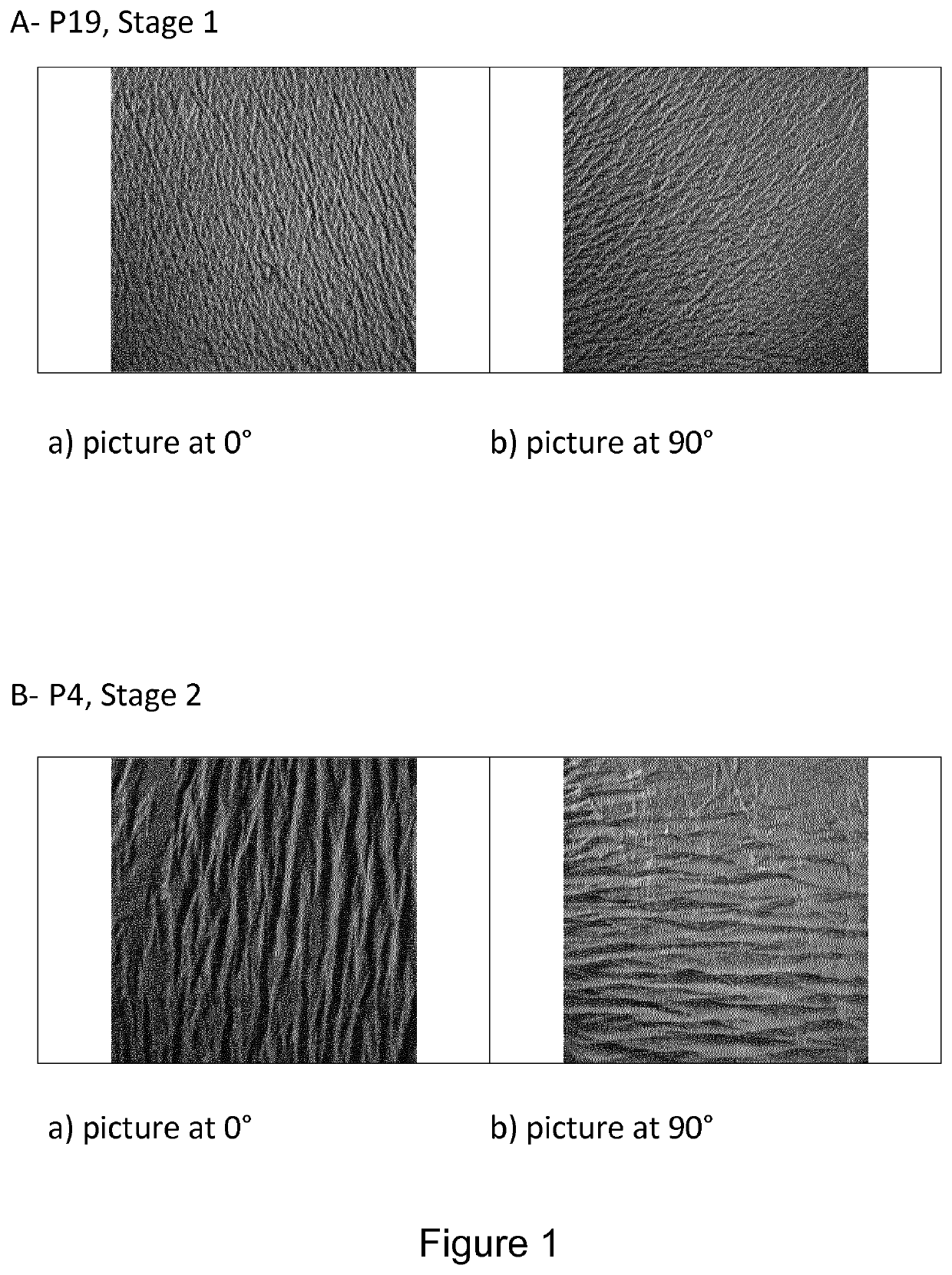
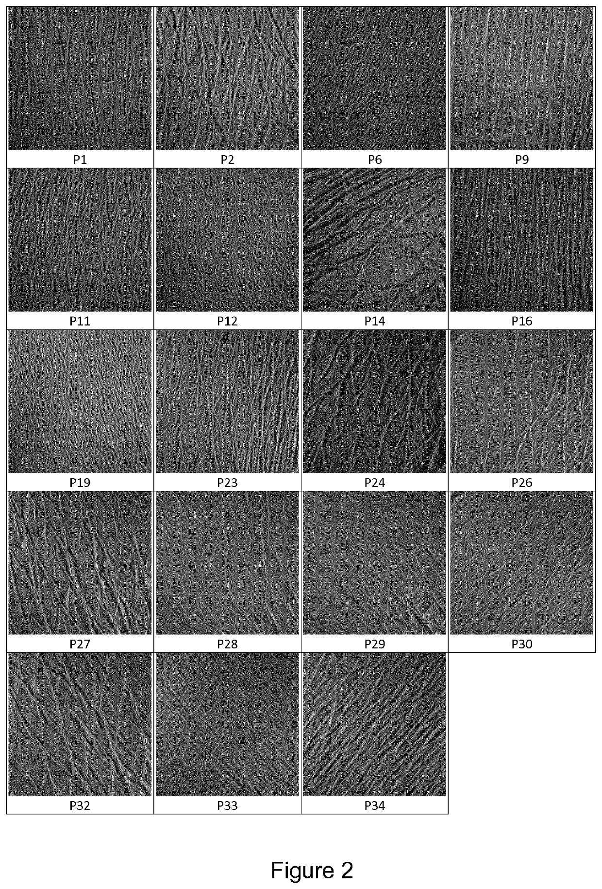
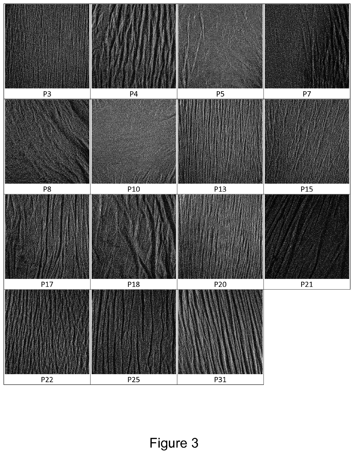
[0229]Using both pictures at 0° and 90°, it is possible to classify visually cutaneous replicas in two groups designated as: [0230] Cutaneous microrelief comprising continuous lines, oriented in multiple directions, are classified as being of “stage 1”; [0231] Cutaneous microrelief comprising short and discontinuous lines, mainly oriented in the same direction, are classified as being “stage 2”.
[0232]An example for both stage 1 and stage 2 is given on FIG. 1 for patients P4 and P19. As shown in this figure, differences between stages 1 and 2 are visible with the naked eye, since microreliefs of stages 1 and 2 present distinct anisotropy and line shape.
[0233]Stage 1 is representative of healthy skins, and stage 2 is representative of altered skins; this last stage is correlated with the natural ageing of the skin and its components.
[0234]Pictures of cutaneous replicas from the 34 patients included in the study have been classified between stages 1 and 2. For visualization, all pictures at 0 degree are given on FIG. 2 and FIG. 3. [0235] 19 replica have been identified as ‘stage 1’ (FIG. 2); [0236] 15 replicas have been identified as ‘stage 2’ (FIG. 3).
[0237]From these two cohorts, replica P8 and P14 are spatially heterogeneous and are eliminated for the further qualitative analyses.
[0238]Application of this Qualitative Classification of the Replica to the Determination of Bone Quality:
[0239]In parallel of the classification of cutaneous replicas, the quality of the femoral head of each patient was explored.
[0240]Indeed, after the fracture, the explanted femoral head had been conserved to be tested with a validated protocol (Berot et al., 2012).
[0241]The mineral density of this femoral head was calculated (C Tan, Bruker MicroCT, Kontich Belgium) and, with a sample of the prelevated sample bone, the limit of the resistance of the bone tissue (bone yield stress) was determined with mechanical tests of monitored compression using the device INSTRON Electropuls 10.000 (Instron World, Norwood, USA).
[0242]Then a mean of the bone yield stress was calculated for both groups previously determined in function of the stage of the skin surface microrelief: [0243] For stage 1 patients, the average bone yield stress value is 13.6+/−4.7 MPa; [0244] For stage 2 patients, the average bone yield stress value is 8.9+/−4.6 MPa.
[0245]The difference in bone yield stress between these two stages, according to the statistical test of Mann-Withney, is significant (p value=0.02).
Example 3
Technique for the Quantitative Classification of Cutaneous Replica, and Application on the Determination of the Bone Quality
[0246]In order to quantify the differences between both stages, and therefore to classify with more details the replicas, a quantitative technique based on the use of an optical sensor was developed. A measurement of the microrelief of each replica picture was realized on a distance of 10 mm, in the longitudinal direction (0°) and the transversal direction (90°) (see FIG. 4A).
[0247]An example of the microrelief obtained by this technique, characterized by the roughness indexes measured in both directions, is presented in FIG. 4B: the cutaneous replica no 16 was assessed as presented above.
[0248]On each roughness profile, x is the distance along the line at the surface of the replica. For each x-value, z corresponds to the distance in the vertical direction between the point at the surface of the replica and the mean line profile.
[0249]From this picture, the number of peaks in the longitudinal direction (Nb_0) and in the transversal direction (Nb_90) can be determined: these numbers give information about the lines shape in each direction.
[0250]Based on these profiles, the roughness index is calculated according to the following equation:
R a = 1 N Σ i = 1 N Zi Equation 2
[0251]wherein N corresponds to the collected points along the measurement direction, and for each point (i), Zi corresponds to the distance in the vertical direction between the surface of the replica and the mean line profile.
[0252]This calcul is computed for each direction at 0° and at 90° and results are designated as Ra_0 and Ra_90, respectively. The sum of these two terms is defined as the SILT which represent the general roughness of the replica:
SILT=Ra_0+Ra_90   Equation 3
[0253]The table 1 below gives the value of SILT calculated for each patient P1 to P34:
TABLE 1 Calculated SILT for each patient - compared to the stage defined visually, and values of bone yield stress Stage (according to Stage Correlation Bone yield Patient SILT SILT value) (visual) visual/SILT stress (MPa) P1 64 1 1 YES 12.5 P2 82 1 1 YES 6.3 P3 42 2 2 YES 1.5 P4 121 2 2 YES 7.6 P5 37 2 2 YES 5.3 P6 60 1 1 YES 13 P7 66 1 2 NO 15.5 P8 117 1 Not done P9 77 1 1 YES 18.5 P10 31 2 2 YES 1.3 P11 54 1 1 YES 11.5 P12 70 1 1 YES 25.4 P13 69 1 2 NO 14.6 P14 167 2 Not done P15 70 1 2 NO 11.9 P16 56 1 1 YES 14.8 P17 131 2 2 YES 6.2 P18 248 2 2 YES 7.5 P19 52 1 1 YES 19.7 P20 67 1 2 NO 12.1 P21 129 2 2 YES 13.5 P22 93 1 2 NO 6.2 P23 45 1 1 YES 9.7 P24 97 1 1 YES 9.1 P25 157 2 2 YES 6.7 P26 57 1 1 YES 13 P27 114 1 1 YES 14 P28 58 1 1 YES 17 P29 118 1 1 YES 10.6 P30 49 1 1 YES 7.7 P31 117 1 2 NO 15 P32 92 1 1 YES 12.5 P33 67 1 1 YES 12 P34 74 1 1 YES 17.8
[0254]Using SILT values, replicas were separated in two groups designated as: [0255] Group “stage 1” corresponds to medium SILT values: values are comprised between 45 μm and 120 μm, or are equal to 45 μm or 120 μm (120≥SILT≥45 μm). [0256] Group “stage 2” corresponds to extreme SILT values: strictly lesser than 45 μm or greater than 120 μm.
[0257]Among the 32 fully evaluated patients, 6 patients (P7, P13, P15, P20, P22, P31) replica were classified visually as being of «stage 2» i.e. having an altered skin. However, after the calculation of the SILT of these replica, and comparison with the reference values defined as above, these patients were re-classified in the group “stage 1”.
[0258]Interestingly, the incorrect visual classification (stage 2 instead of stage 1) leads to a positive re-qualification of the patients, who were finally classified as being “stage 1” after determining the roughness index of the microrelief of their cutaneous replica.
[0259]Compressive bone yield stress values are given for comparison, because this parameter is usually considered as one of good biomarker of the bone quality; however, this measure shall not be considered, by itself, as giving a definitive opinion on the quality of the bone.
[0260]As presented in example 2, for each group the mean value of the bone yield stress was calculated and is presented in FIG. 5A: [0261] For patients with medium SILT (stage 1), the bone yield stress mean is 13.35+/−4.3 MPa. [0262] For patients with extreme SILT (stage 2), the bone yield stress mean is 6.18+/−3.8 MPa.
[0263]As shown in FIG. 5A, a relevant difference in bone yield stress is noted between both groups, according to the statistical test of Mann-Withney (p=4.1 10−3).
[0264]FIG. 5B shows the mean of each group for the Young's modulus, another marker of the solidity of the bones.
[0265]Results for each group are presented in the following table 2:
TABLE 2 Young's modulus mean for each group of patients Young's modulus (MPa) Medium SILT 910 +/− 398 Extreme SILT 535 +/− 267 p-value 0.017

PUM

no PUM

Description & Claims & Application Information

We can also present the details of the Description, Claims and Application information to help users get a comprehensive understanding of the technical details of the patent, such as background art, summary of invention, brief description of drawings, description of embodiments, and other original content. On the other hand, users can also determine the specific scope of protection of the technology through the list of claims; as well as understand the changes in the life cycle of the technology with the presentation of the patent timeline. Login to view more.

Similar technology patents

Method and apparatus for obtaining binocular panoramic image, and storage medium

PendingUS20210075963A1rapidly calculatelow quality
Owner:TENCENT TECH (SHENZHEN) CO LTD

Recording apparatus

ActiveUS9248679B1low quality
Owner:OKI ELECTRIC IND CO LTD

Method of determining shared service index based on shared service of communication credential

PendingUS20210385634A1advantageous effectlow quality
Owner:SHENZHEN UCLOUDLINK NETWORK TECH CO LTD

Image forming apparatus

ActiveUS20180282088A1low quality
Owner:BROTHER KOGYO KK

Classification and recommendation of technical efficacy words

  • low quality

Capsule for Preparing Drinks

ActiveUS20100108541A1low quality
Owner:CAFFITAL SYST SPA

Light coupler and fiber laser system including the same

ActiveUS20100111118A1low quality
Owner:ELECTRONICS & TELECOMM RES INST

Adaptive optic beamshaping in laser processing systems

InactiveUS20100059490A1reduce sensitivitylow quality
Owner:ELECTRO SCI IND INC

Display apparatus and control method thereof

InactiveUS20070285380A1low quality
Owner:SAMSUNG ELECTRONICS CO LTD
Why Eureka
Try Eureka