Door handle

a door handle and handle technology, applied in the field of door handles, can solve the problems of safety accidents and inconveniences in use, and achieve the effect of protecting the user's fingers from safety accidents

Active Publication Date: 2018-10-04
SEO WON KOREA
View PDF9 Cites 4 Cited by
  • Summary
  • Abstract
  • Description
  • Claims
  • Application Information

AI Technical Summary

Benefits of technology

[0013]According to the present invention, the door handle can tilt upward at the time when it is held to pull so as to initially open a door, thereby preventing a user's fingers from being caught in a space between the door and the door handle, and can be slowly returned to an initial state thereof through resistance of a damper at the time when the tilted door handle is returned to the initial state by means of a tension force of a spring, so that even if a user's fingers are caught in a space between the door handle and a door, the door handle can protect the user's fingers from safety accidents.

Problems solved by technology

According to the prior art, if the door handle is held and pulled down to open a cooking compartment of the oven, the door handle itself further moves downward, and since the door handle is fixed to the door, at this time, a rotating angle of the door handle becomes increased according to an opening operation of the door, so that a user's wrist holding the door handle may be bent to undesirably cause many inconveniences in use.
If it is desired that the door is initially open in the state where it is closed, particularly, the user's fingers may be caught in a space between the door and the door handle, and at this time, if the door is open in the state where the user's fingers are caught in the space, safety accidents may happen.

Method used


Image

  • Door handle
  • Door handle
  • Door handle

Examples


Embodiment Construction

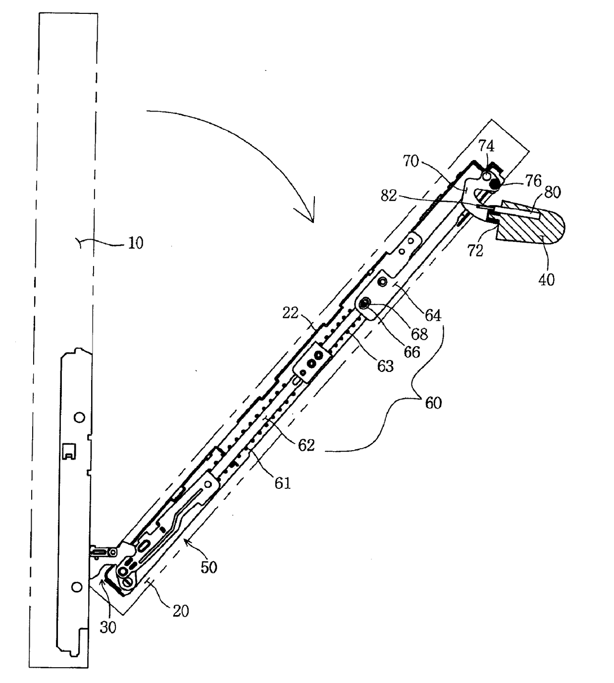
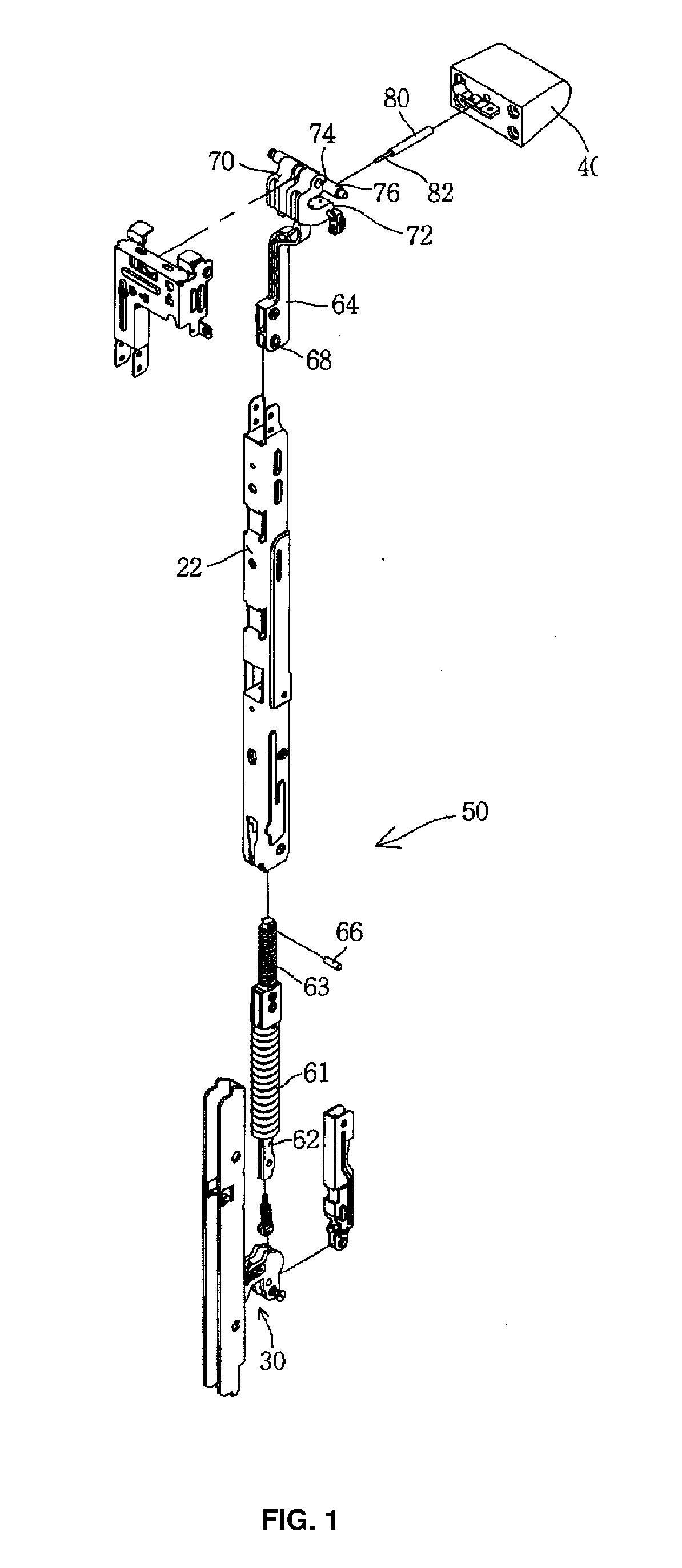
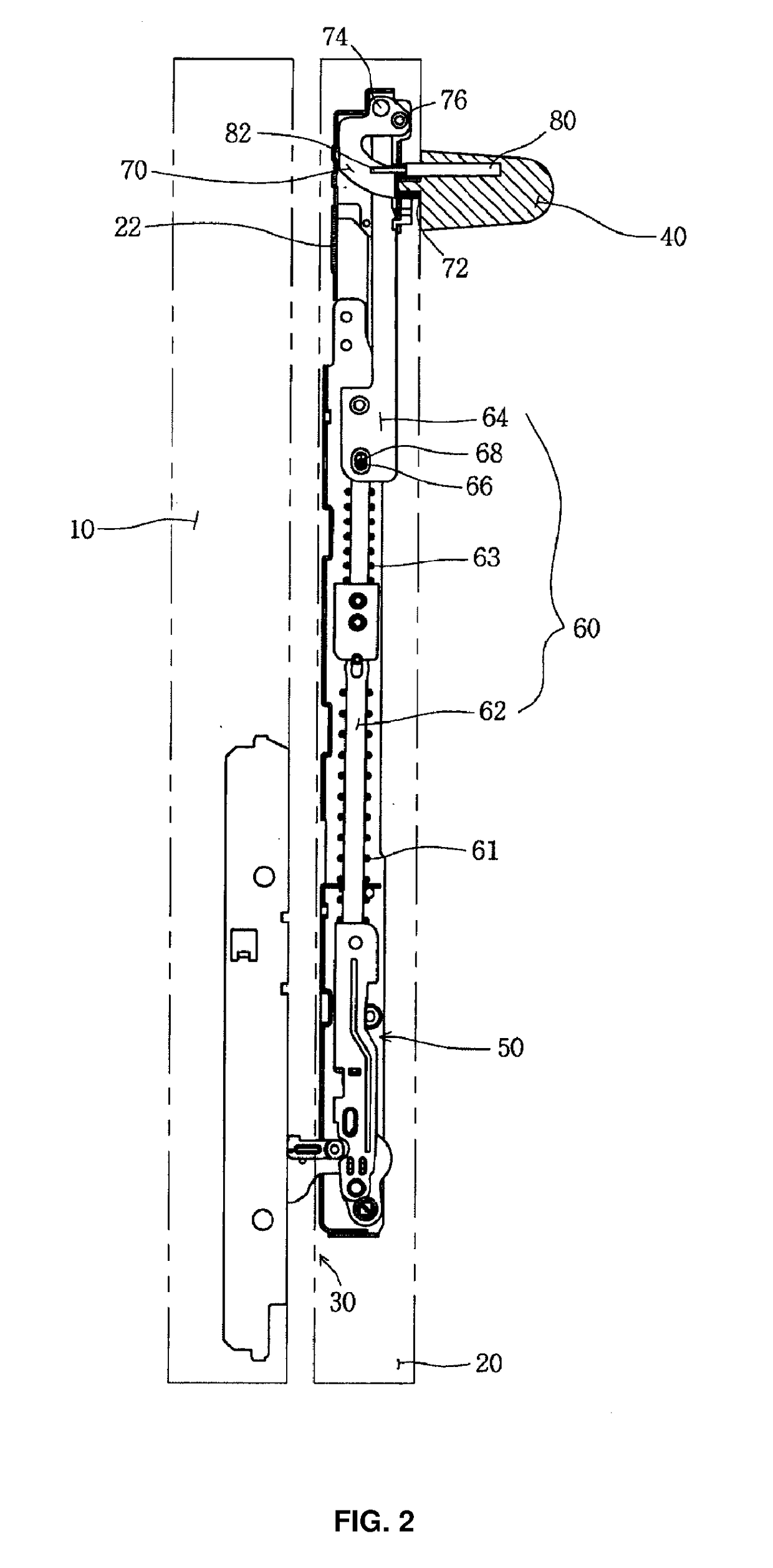
[0022]According to the present invention, there is provided a door handle located on an upper end of a front surface of a door for opening and closing a body so as to open and close a cooking compartment formed inside the body at the time when the door pulls and rotates around door hinges, the door handle including a first actuating rod disposed in a vertically erected state on each of both sides of the door and having an end connected to the corresponding door hinge in such a manner as to be movable upward and downward, a second actuating rod disposed above the first actuating rod and coupled to a front end of the first actuating rod by means of a pin, a rotating member having an end coupled to the door handle and a front end coupled to the second actuating rod by means of a pin, and a hinge pin having both ends coupled to a door bracket fixed to the door after passing through the front end of the rotating member, wherein the second actuating rod has an elongated hole formed on a l...


PUM


Abstract

The present invention relates to a door handle that tilts upward when a door is open initially, and after the tilting has been completed, is slowly returned to an initial state thereof through the resistance of a damper, so that even if a user's fingers are caught in a space between the door handle and the door, the door handle can protect the user's fingers from safety accidents. According to the present invention, the door handle is located on an upper end of a front surface of a door for opening and closing a body so as to open and close a cooking compartment formed inside the body at the time when the door pulls and rotates around door hinges, and the door handle includes a first actuating rod disposed in a vertically erected state on each of both sides of the door and having an end connected to the corresponding door hinge in such a manner as to be movable upward and downward, a second actuating rod disposed above the first actuating rod and coupled to a front end of the first actuating rod by means of a pin, a rotating member having an end coupled to the door handle and a front end coupled to the second actuating rod by means of a pin, and a hinge pin having both ends coupled to a door bracket fixed to the door after passing through the front end of the rotating member, wherein the second actuating rod has an elongated hole formed on a lower end thereof so as to allow the pin for connecting the first actuating rod and the second actuating rod to be fitted thereto in such a manner as to be movable upward and downward.

Description

REFERENCE TO RELATED APPLICATIONS[0001]This is a continuation of International Patent Application PCT / KR2016 / 012573 filed on Nov. 3, 2016, which designates the United States and claims priority of Korean Patent Application No. 10-2015-0173775 filed on Dec. 8, 2015, the entire contents of which are incorporated herein by reference.FIELD OF THE INVENTION[0002]The present invention relates to a door handle and, more particularly, to a door handle that tilts upward when a door is initially open, and after the tilting operation has been completed, that is slowly returned to an initial state thereof through the resistance of a damper, so that even if a user's fingers are caught in a space between the door handle and the door, the door handle can protect the user's fingers from safety accidents.BACKGROUND OF THE INVENTION[0003]Generally, an oven as one of electric home appliances serves to cook an object put in a cooking compartment formed at the inside thereof by means of heat generated f...

Claims


Application Information

Patent Timeline
Patent Type & Authority Applications(United States)
IPC IPC(8): F24C15/02E05B1/00
CPCF24C15/02E05B1/0015E05B7/00F24C15/024Y10T292/57
Inventor LEE, JUNEYOUNG
Owner SEO WON KOREA
Why Eureka
Try Eureka