Honing material taking device and material taking method thereof

A material retrieving device and honing technology, which is applied in the direction of honing machine tools, grinding feed movement, grinding machine tool parts, etc., can solve the problems of low efficiency, pollution of honing oil, poor safety, etc., and achieve high safety and increased use Lifespan, finger protection effect

Active Publication Date: 2019-12-03
安徽多邦珩磨技术有限公司
View PDF12 Cites 0 Cited by
  • Summary
  • Abstract
  • Description
  • Claims
  • Application Information

AI Technical Summary

Problems solved by technology

[0006] Aiming at the problems of low efficiency, poor safety and pollution of honing oil in the existing honing retrieving method, the present invention provides a honing retrieving device and its retrieving method. By using the honing retrieving The device replaces the staff's fingers to pick up materials, and the operation is simple, safe, labor-saving, high in efficiency, and will not pollute the honing oil

Method used


Image

  • Honing material taking device and material taking method thereof
  • Honing material taking device and material taking method thereof
  • Honing material taking device and material taking method thereof

Examples


Embodiment 1

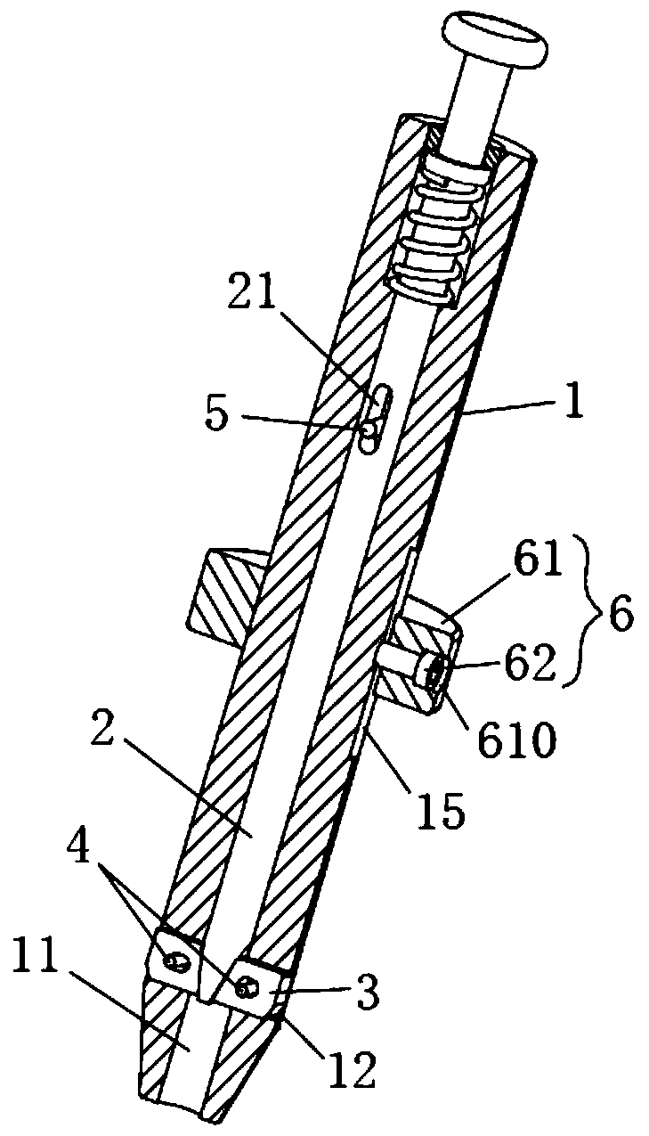
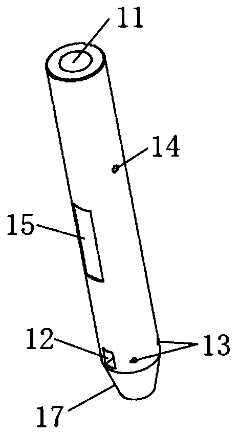
[0044] Such as figure 1As shown in , a honing and reclaiming device in this embodiment includes a cylindrical housing 1, which has a central hole 11 penetrating along its axial direction, and the lower part of the housing 1 has a At least one slider installation hole 12 radially penetrating to the central hole 11, preferably 2 to 4, and evenly distributed around the central axis of the housing 1; and the same number of slider installation holes 12 A slider 3, the slider 3 is movably installed in the slider mounting hole 12; and a movable push rod 2 inserted in the central hole 11, the movable push rod 2 is movable with the housing 1 Connection; push the movable push rod 2 to the lower end of the housing 1 along the central hole 11, and the movable push rod 2 squeezes the slider 3 so that the slider 3 moves along the slider installation hole 12 slides outward and pops out of the housing 1.

[0045] In this example, if figure 1 , 3 As shown in and 6, the slider 3 has a horiz...

Embodiment 2

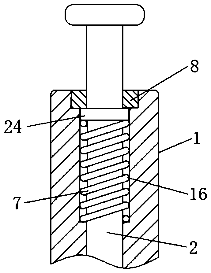
[0056] A kind of honing pick-up device of present embodiment, its basic structure is the same as in embodiment 1, and difference and improvement are, as figure 2 As shown in , the upper end of the housing 1 has an outer hole 16, and the outer hole 16 is provided with a return spring 7, and the return spring 7 is sleeved on the movable push rod 2, and the outer wall of the movable push rod 2 There is a boss 24 on the top, and the boss 24 is located at the upper end of the return spring 7; the entrance of the outer hole 16 is fixed with an annular pressure plate 8, which is used to block the movable push rod 2 in the housing 1 without being blocked. pull out.

[0057] After the workpiece 100 is transferred to the specified position according to the method of taking material in the embodiment 1, release the thumb, and the movable push rod 2 is pushed up by the rebound effect of the return spring 7, so that it is separated from the slide block 3, so that Therefore, the slide blo...

Embodiment 3

[0060] A kind of honing pick-up device in the present embodiment, its basic structure is the same as embodiment 1 or 2, and difference and improvement are, as Figure 4 , 5 , 6, the inner end of the slider 3 has an inclined surface 32, the lower end of the movable push rod 2 has an inclined surface 22 or a tapered surface 23 that cooperates with the inclined surface 32, and through the inclined surface 22 or the tapered surface The surface 23 cooperates with the inclined surface 32 on the slider 3, so that the movable push rod 2 can be inserted into the gap between the sliders 3 more easily, and in the process of pushing the movable push rod 2, the slider 3 can be slowly slid out of the slider The holes 12 are installed to prevent the slider 3 from moving too fast and hitting the inner wall of the workpiece 100 to cause damage.


PUM


Abstract

The invention discloses a honing material taking device and a material taking method thereof, and belongs to the technical field of honing machining. The honing material taking device comprises a cylindrical shell; a center hole penetrating through the shell in the axis direction of the shell is formed in the shell, and at least one sliding block mounting hole penetrating through the center hole in the radial direction is formed in the lower portion of the shell; sliding blocks with the number same as that of the sliding block mounting holes are movably mounted in the sliding block mounting holes; a movable push rod is inserted into the center hole and is movably connected with the shell; the movable push rod is pushed to the lower end of the shell along the center hole, and the movable push rod extrudes the sliding blocks to enable the sliding blocks to slide outwards along the sliding block mounting holes and protrude out of the shell. During material taking, the honing material taking device is inserted into a workpiece, the upper end of the movable push rod is pressed, the sliding blocks are extruded out through the movable push rod and abut against the inner wall of the workpiece, and therefore the workpiece is taken out of a honing clamp. According to the honing material taking device, the honing material taking device is used for replacing finger material taking of workers, the operation is easy, safe and labor-saving, efficiency is high, and honing oil cannot be polluted.

Description

technical field [0001] The invention relates to the technical field of honing processing, in particular to a honing retrieving device and a retrieving method thereof. Background technique [0002] The honing process (including honing reaming and reaming honing process) is a processing technology for superfinishing the surface of the inner hole of the workpiece with a honing tool. During honing, the workpiece is installed on the honing machine table or in a special fixture, and the honing tool is inserted In the rough-machined bottom hole, the honing tool is driven by the spindle of the machine tool to rotate and reciprocate in the axial direction. The honing rod on the honing tool contacts the wall of the hole to be machined with a certain pressure, and a very thin layer of metal can be cut off. Therefore, the bad shape of the inner hole is cut off, and the machining accuracy of the hole is improved. [0003] After the workpiece honing process is completed, the workpiece ne...

Claims


Application Information

Patent Timeline
Patent Type & Authority Applications(China)
IPC IPC(8): B24B33/10B24B41/00
CPCB24B33/10B24B41/005
Inventor 吴腾英吴学应
Owner 安徽多邦珩磨技术有限公司
Why Eureka
Try Eureka