Movement with power reserve extension

a technology of power reserve and extension device, which is applied in the direction of instruments, horology, gearworks, etc., to achieve the effect of reducing the thickness of the movement, reducing the energy consumption of the movement, and avoiding excessive thickness of the movement and therefore of the watch

Active Publication Date: 2018-10-04
THE SWATCH GRP RES & DEVELONMENT LTD
View PDF7 Cites 1 Cited by
  • Summary
  • Abstract
  • Description
  • Claims
  • Application Information

AI Technical Summary

Benefits of technology

[0010]More specifically, it is an object of the invention to provide a movement for timepieces can obtain a better power reserve by limiting the energy consumption of the movement when it is not being worn or is in a rest position.
[0011]It is also an object of the invention, at least in a particular embodiment, to avoid excessive thickness of the movement and therefore of the watch.

Problems solved by technology

Such proposed solutions to overcome the problem of increasing power reserve are of little interest, because the power reserve is given priority at the expense of available space.

Method used


Image

  • Movement with power reserve extension
  • Movement with power reserve extension
  • Movement with power reserve extension

Examples


Embodiment Construction

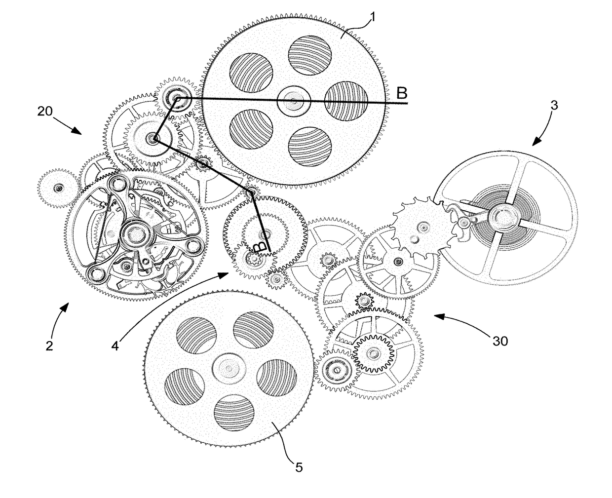
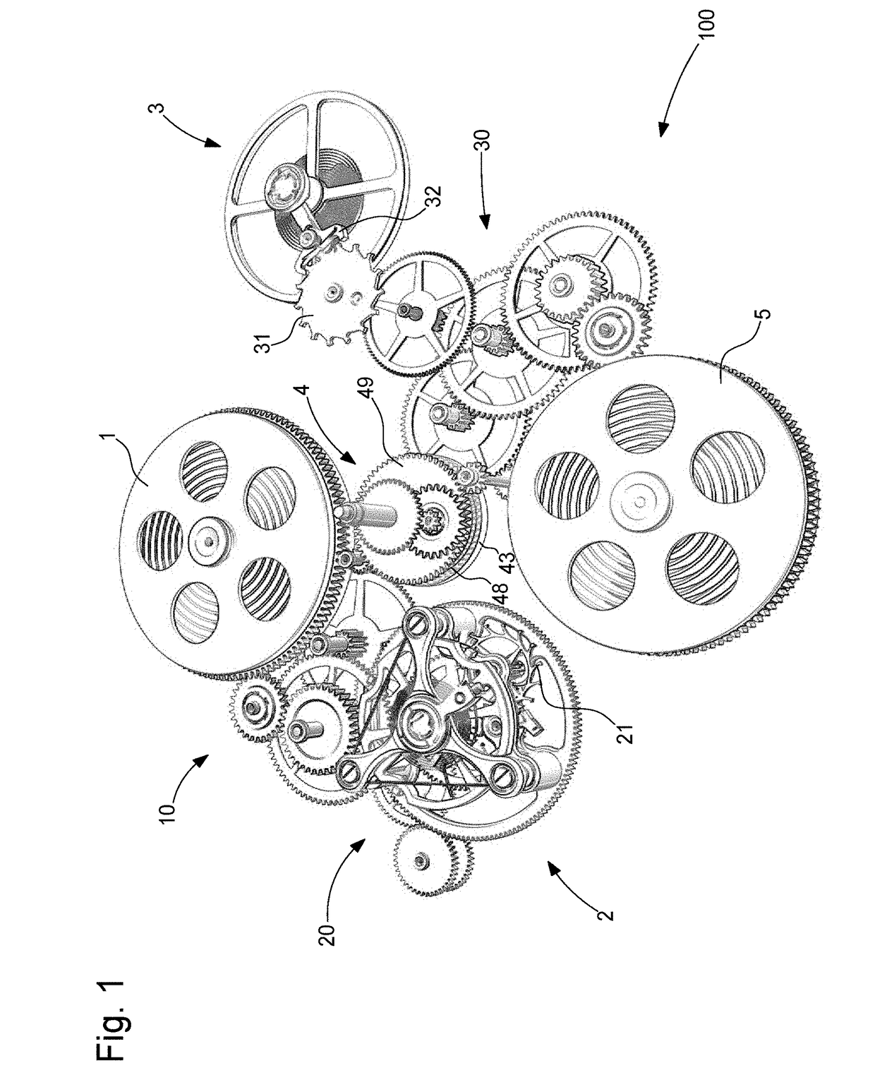
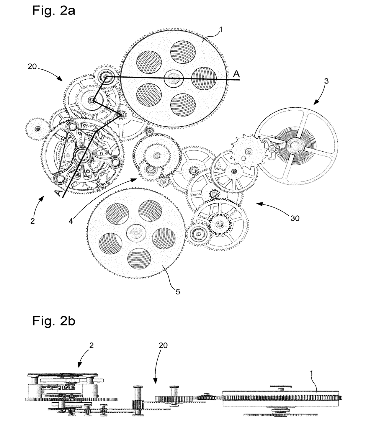
[0033]A timepiece movement according to the invention will be described below referring jointly to FIGS. 1, 2a, 2b, 3a, 3b, 4a, 4b, 5a, 5b, 6a, 6b, 7a, 7b and 7c.

[0034]The movement according to the invention comprises a first regulating member and a first escapement connected by a first train to a first energy source, the first train, the first escapement, the first regulating member and the first energy source defining a first assembly, a second regulating member and a second escapement connected by a second train to a second energy source, the second train, the second escapement, the second regulating member and the second energy source defining a second assembly, at least one differential gear provided to ensure a kinematic connection between the first assembly and the second assembly, and means for displaying the current time.

[0035]Further, the timepiece movement includes means for stopping and allowing operation of one of the two regulating members, and the differential gear c...


PUM


Abstract

The invention relates to a timepiece movement comprising a first regulating member and a first escapement connected by a first train to a first energy source, the first train, the first escapement, the first regulating member and the first energy source defining a first assembly, a second regulating member and a second escapement connected by a second train to a second energy source, the second train, the second escapement, the second regulating member and the second energy source defining a second assembly, at least one differential gear provided to ensure a kinematic connection between the first assembly and the second assembly, and means for displaying the current time. According to the invention, the timepiece movement includes means for stopping and allowing operation of one of the two regulating members, and the differential gear carries the time display means to display the time regardless of which regulating member is operating.

Description

[0001]This application claims priority from European Patent Application No. 17163951.1 filed on Mar. 30, 2017; the entire disclosure of which is incorporated herein by referenceFIELD OF THE INVENTION[0002]The invention relates to a timepiece movement comprising a power reserve extension device, to limit the energy consumption of the movement when the watch is not worn, or in a rest position.BACKGROUND OF THE INVENTION[0003]Usually, in mechanical watches, the energy source for driving the train and the hands, and other functions, is a spiral spring wound inside a barrel.[0004]When a mechanical watch is not wound regularly, or when a self-winding watch is not worn for several hours, the watch spring is completely let down, and the watch stops. The average power reserve of a normal watch whose mainspring is completely wound is around 40 to 60 hours.[0005]There are several reasons for a watch to discharge energy until it stops, especially not wearing a watch for some time (storage, week...

Claims


Application Information

Patent Timeline
Patent Type & Authority Applications(United States)
IPC IPC(8): G04B19/02G04B17/28G04B17/06G04C3/08
CPCG04B19/02G04B17/285G04B17/06G04C3/08G04B1/10G04B1/16G04B1/12G04B1/145G04B13/02
Inventor BAZIN, JEAN-LUCBRAVO, PAULO
Owner THE SWATCH GRP RES & DEVELONMENT LTD
Why Eureka
Try Eureka