Air conditioner for vehicles and method of controlling same

a technology for air conditioners and vehicles, applied in the field of vehicles, can solve the problems of inability to obtain the necessary amount of dehumidification, excessive inability to control the cooling ability of evaporators, so as to avoid condensation on the window glass and limit energy consumption

Inactive Publication Date: 2007-11-20
KEIHIN CORP
View PDF12 Cites 13 Cited by
  • Summary
  • Abstract
  • Description
  • Claims
  • Application Information

AI Technical Summary

Benefits of technology

[0011]It is a general object of the present invention to provide a vehicular air conditioner which is capable of controlling the interior of a passenger compartment at an appropriate temperature and humidity, avoiding condensation on the window glass, and limiting energy consumption to a required minimum, and a method of controlling such a vehicular air conditioner.
[0012]A major object of the present invention is to provide a vehicular air conditioner which is capable of controlling the temperature and humidity in a passenger compartment without fogging the windows, using the cooling capacity of a compressor as a required minimum, and a method of controlling such a vehicular air conditioner.

Problems solved by technology

If the temperature of ejected air that is necessary for controlling the temperature in the passenger compartment at the preset temperature is lower than the temperature of ejected air that produces the humidity in the passenger compartment that will not cause window condensation, then since the humidity in the passenger compartment is high even if the temperature in the passenger compartment is close to the preset temperature, the passengers in the passenger compartment may feel uncomfortable.
If the humidity of exterior air that enters the passenger compartment is not taken into account in the process of determining the temperature of ejected air that produces the humidity in the passenger compartment that will not cause window condensation, because the necessary humidity of ejected air cannot be calculated highly accurately on account of a humidity change caused by the humidity of introduced exterior air, the cooling ability of the evaporator may possibly be excessively controlled or the necessary amount of dehumidification cannot be obtained.

Method used


Image

  • Air conditioner for vehicles and method of controlling same
  • Air conditioner for vehicles and method of controlling same
  • Air conditioner for vehicles and method of controlling same

Examples


Embodiment Construction

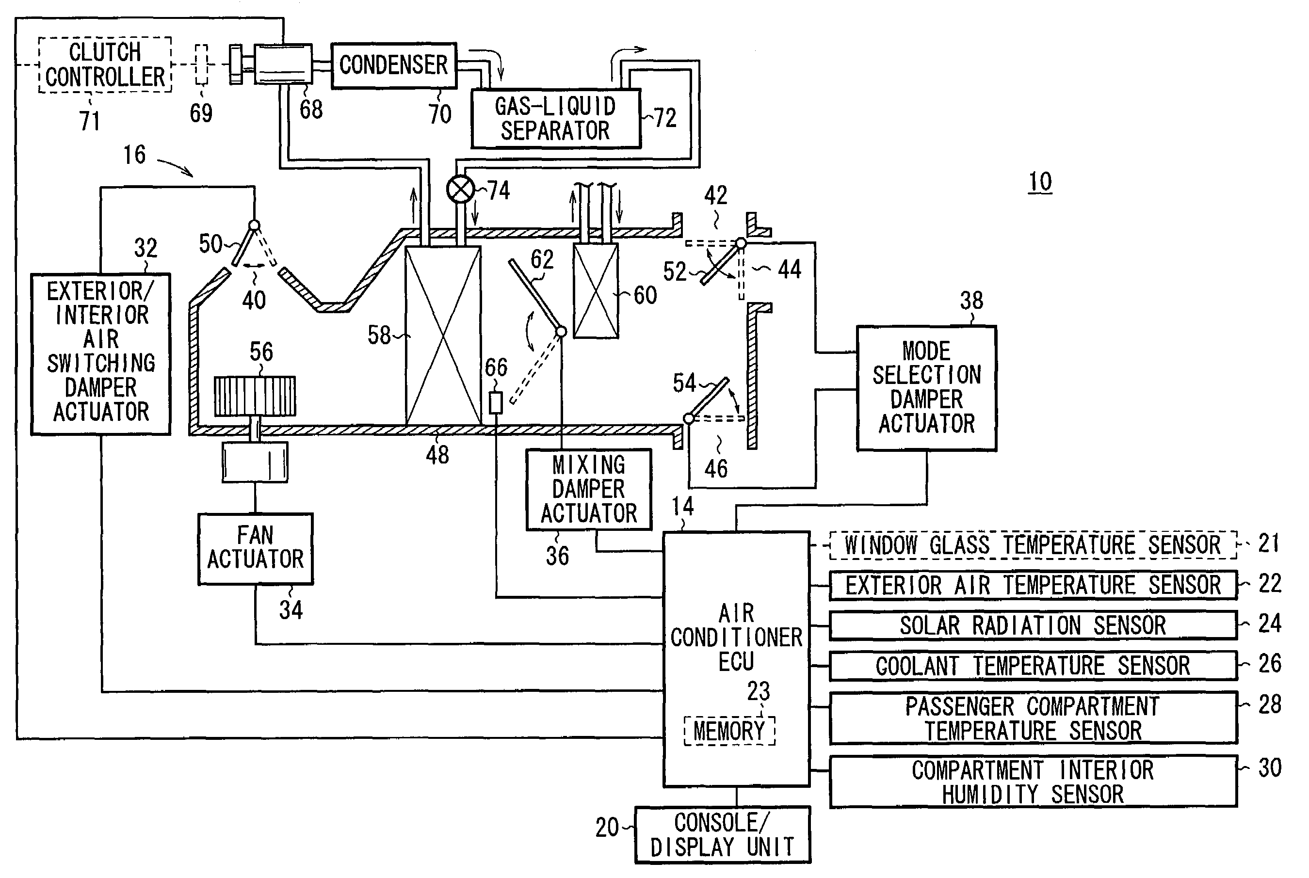
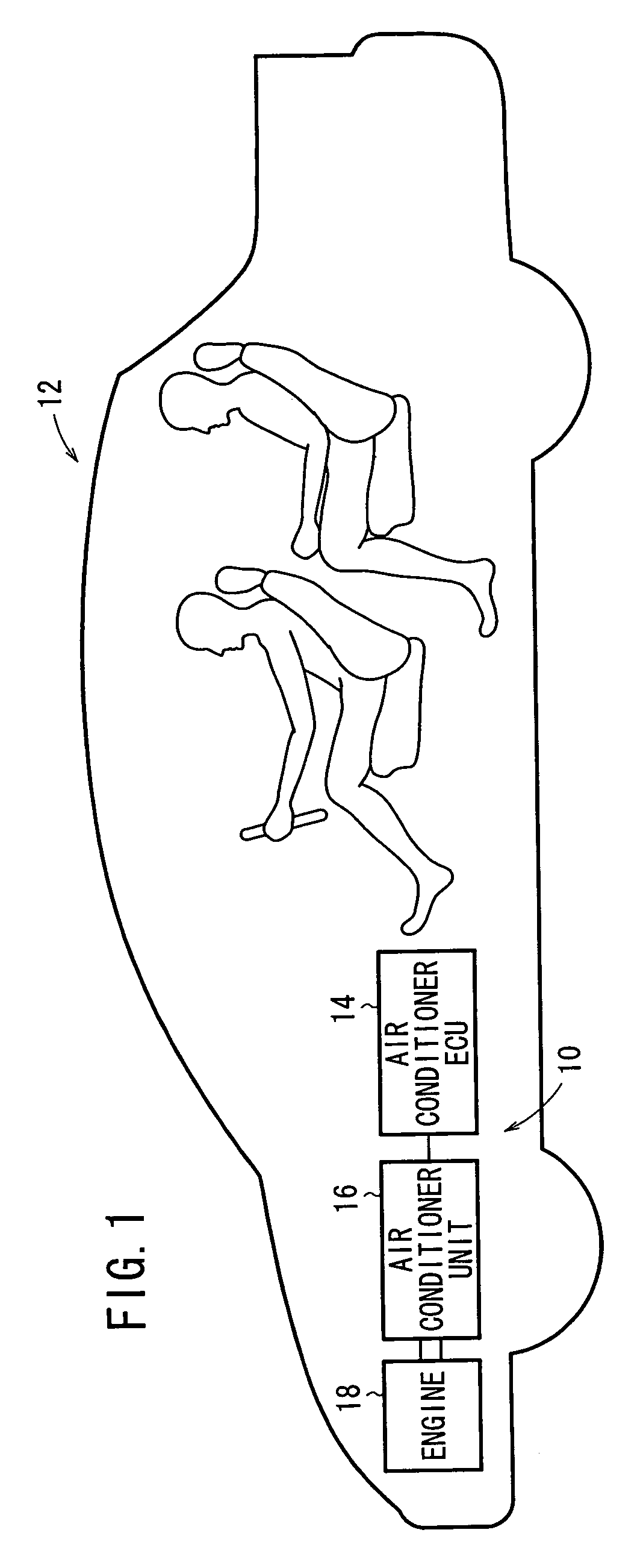
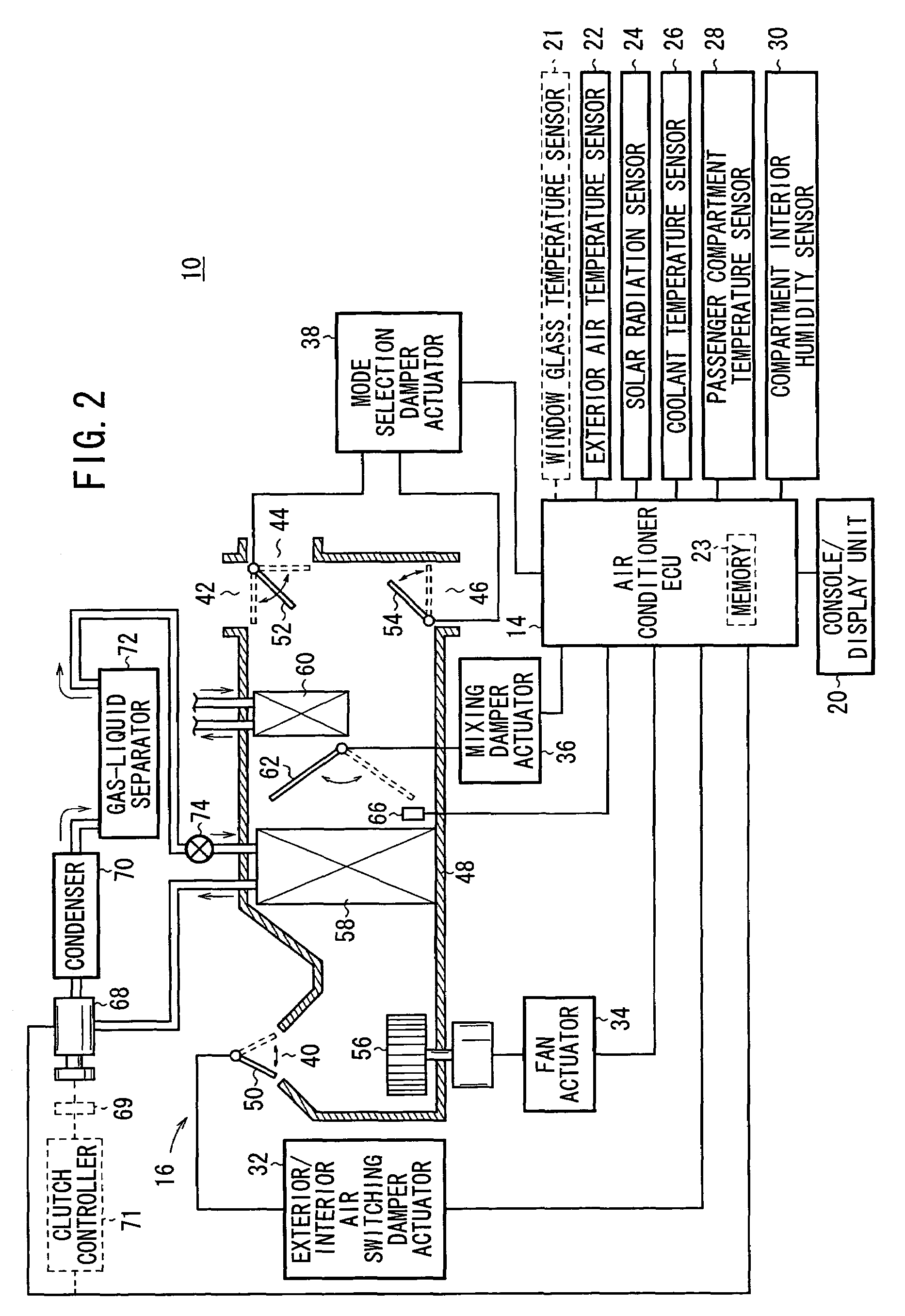
[0020]FIG. 1 schematically shows a vehicle 12 incorporating a vehicular air conditioner 10 according to the present invention, and FIG. 2 shows the vehicular air conditioner 10 in detail. As shown in FIG. 1, the vehicular air conditioner 10 comprises an air conditioner ECU (Electronic Control Unit) 14, and an air conditioner unit 16 controlled by the air conditioner ECU 14 for adjusting the temperature and humidity of air and the quantity of supplied air. The air conditioner unit 16 is supplied with a coolant from an engine 18 which propels the vehicle 12.

[0021]As shown in FIG. 2, to the air conditioner ECU 14, there is connected a console / display unit 20 which receives control inputs representative of a temperature setting, an amount-of-supplied-air setting, a mode selection, etc. entered by a passenger on the vehicle 12 and displaying a set temperature, a set amount of supplied air, and a selected mode.

[0022]To the air conditioner ECU 14, there are also connected an exterior air t...


PUM


Abstract

A window glass dew-point compartment interior absolute humidity Xrmax is acquired, and a temporary compartment interior set absolute humidity Xset (temporary Xset) is determined from a compartment interior set temperature Tset. A smaller one of Xrmax and (temporary Xset) is used as a compartment interior set absolute humidity Xset. An outlet air required absolute humidity Xao required to obtain Xset is calculated taking into account the humidity of exterior air introduced into the passenger compartment. Using Xao and an outlet air required temperature Tao required to obtain Tset, a control temperature Tea for controlling a compressor is determined.

Description

BACKGROUND OF THE INVENTION[0001]1. Field of the Invention[0002]The present invention relates to a vehicular air conditioner for controlling a cooling means and a heating means to adjust the temperature and humidity in a passenger compartment without fogging the window glass.[0003]2. Description of the Related Art[0004]Vehicular air conditioners have in combination an evaporator for cooling and dehumidifying air by utilizing the heat of vaporization of a refrigerant and a heater for heating air with the heat of an engine coolant to adjust the temperature and humidity in the passenger compartment of a vehicle.[0005]If the vehicular air conditioner is controlled to lower the cooling ability of the evaporator at a low atmospheric temperature, then since the dehumidifying ability of the evaporator is also lowered, the water vapor in the passenger compartment is possibly condensed on the window glass, etc. when the atmospheric temperature is low and the atmospheric humidity is high.[0006...

Claims


Application Information

Patent Timeline
Patent Type & Authority Patents(United States)
IPC IPC(8): B60H1/00B60H1/32
CPCB60H1/0075B60H1/3207B60H1/00785B60H2001/3245
Inventor YONEKURA, MITSURUITOH, SHIGENOBU
Owner KEIHIN CORP
Why Eureka
Try Eureka