Portable electric blower with low reaction torque

a technology of reaction torque and blower, which is applied in the field of blowers, can solve the problems of not being able to correct dynamically the distribution of mass or the positioning of the handle, and not being able to counterbalance the torque generated by this force, so as to improve the efficiency of the channel, reduce the noise of the air intake, and improve the effect of the torque counterbalan

Active Publication Date: 2018-10-11
PELLENC SA
View PDF0 Cites 4 Cited by
  • Summary
  • Abstract
  • Description
  • Claims
  • Application Information

AI Technical Summary

Benefits of technology

[0068]The blower may be equipped, besides the lattice of directional channels, with air deflectors arranged in the vicinity of the intake mouth. The deflectors are located upstream of the lattice of directional channels. The deflectors increase the efficiency of the channels and further reduce the air intake noises.
[0069]In the construction of the blower it can be advantageous to see to it that the distance between the intake axis and the midpoint of equilibrium of the handle is greater than a distance between the fan axis and the midpoint of equilibrium of the handle.
[0070]This measure allows, independently from the lattice of directional channels, to obtain a better counterbalance of the torque at the point of equilibrium of the handle. In effect, since the force of reaction to the intake air flow is weaker than the force of reaction to the blowing air flow, it is possible to partly counterbalance this disparity by means of a stronger leverage for the force of reaction to the intake air flow.

Problems solved by technology

It is not possible to counterbalance the torque generated in reaction to the air flow of the blower simply through a different distribution of the blower masses or by relocating the handle relative to the point of equilibrium.
Now, it is not possible to correct dynamically the distribution of the masses or the positioning of the handle, depending on the reaction force of the air flow, to counterbalance the torque generated by this force.
The torque exerted on the operator's hand thus leads to muscular fatigue while operating the blower.
This is in addition to the fatigue caused by the weight of the blower and the recoil force caused by the air blast.
It reduces the time and comfort of use of the blower.

Method used


Image

  • Portable electric blower with low reaction torque
  • Portable electric blower with low reaction torque
  • Portable electric blower with low reaction torque

Examples


Embodiment Construction

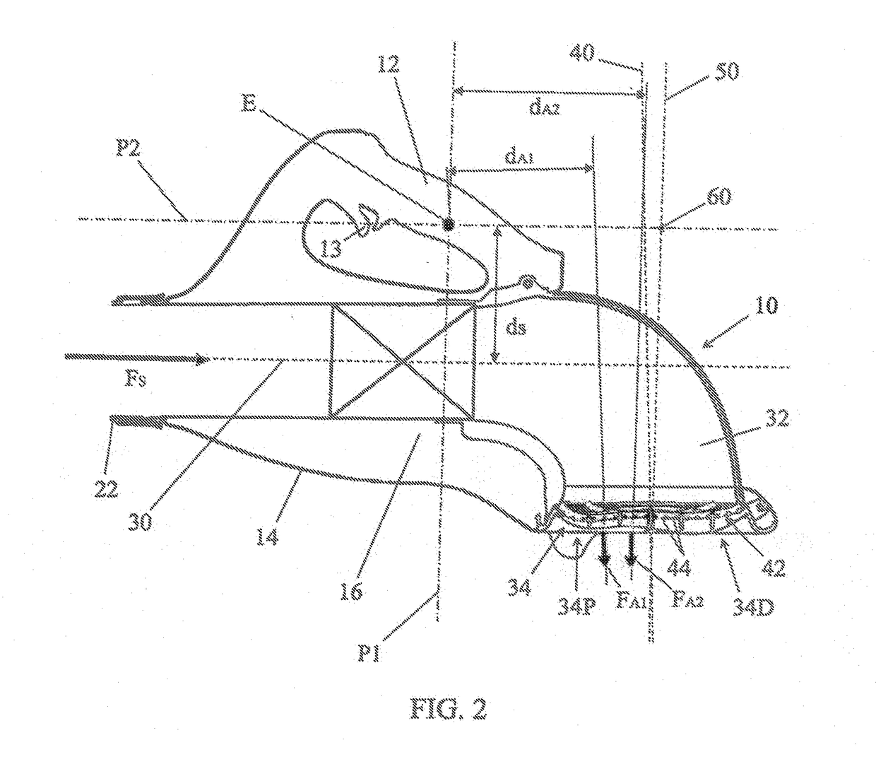
[0089]In the description below identical, equivalent or comparable parts of the various figures are identified by the same reference marks in order to facilitate referring from one figure to another.

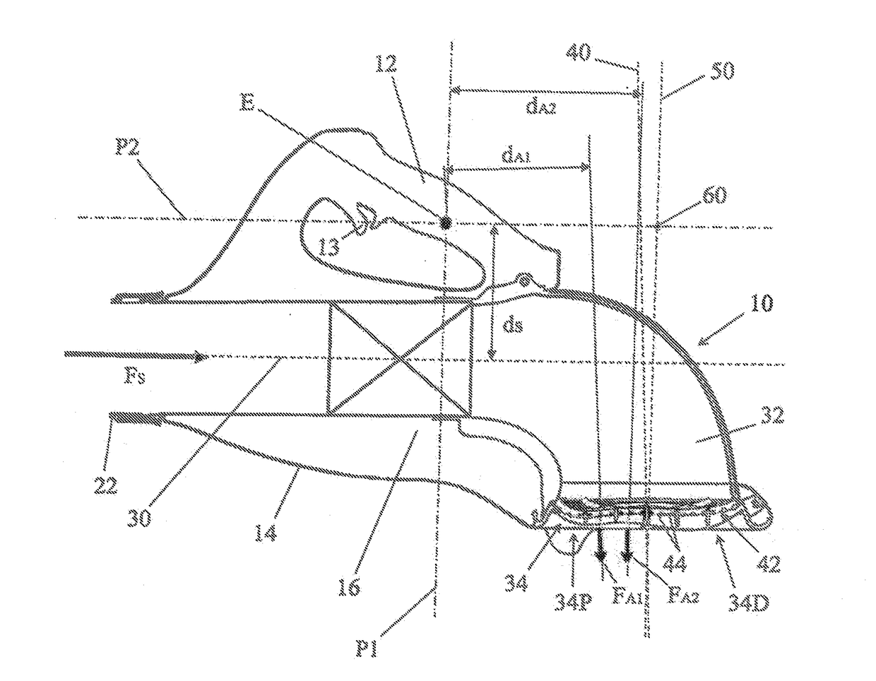
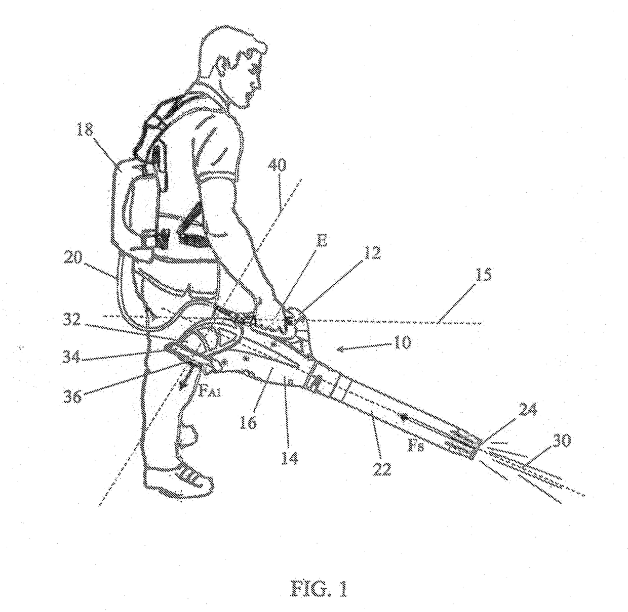
[0090]FIG. 1 shows a blower 10 of the type known, and in particular known through the document FR2964987 previously mentioned to which the invention can be advantageously applied. The blower of FIG. 1 presents a large number of characteristics in common with the blower according to the invention and described in reference to the following figures. One can thus refer to FIG. 1 for the common characteristics.

[0091]FIG. 1 shows the blower as it is being carried and operated by an operator in a normal position of use for the sweeping of dry leaves. The operator holds the blower by a handle 12 fitted into the upper part of a main casing 14 of the blower.

[0092]The main casing 14 essentially contains an axial blower fan 16 for the purpose of creating an air flow. The blower fan is driven by an ...


PUM


Abstract

A portable blower has an axial fan blower, a handle that has a midpoint of equilibrium, a blowing outlet that is connected downstream of the axial fan, at least one suction nozzle that is connected upstream of the axial fan and has an air intake mouth. The air intake nozzle includes a network of directional channels for homogenizing a flow of intake air, the network of directional channels being formed in the vicinity of the air intake mouth. The blower is particularly useful in the field of portable electric blowers for the maintenance of public spaces.

Description

TECHNICAL FIELD[0001]The present invention concerns a blower and in particular a portable electric blower with low reaction torque.[0002]A blower means an air projection device used for sweeping away dry leaves or debris likely to be scattered about the surfaces of lawns, playgrounds, parking lots or public roadways.[0003]Such a device is used primarily for pushing dry leaves or debris into piles that can then more easily be gathered up and removed. Use of a blower may replace a rake or broom. However, it provides greater efficiency while being less laborious.[0004]The invention finds applications for blowers with thermal engines or with electric motors. It is particularly intended for portable, cordless and lightweight blowers that can be carried and operated with one hand.[0005]Portable electric blowers of this type may preferably be equipped with a power supply provided by an integrated or remote battery. A remote battery can be worn on the back or at the belt and be connected to...

Claims


Application Information

Patent Timeline
Patent Type & Authority Applications(United States)
IPC IPC(8): F04D29/70F04D19/00F04D29/54F04D25/06A01G20/47E01H1/08
CPCF04D29/703F04D19/002F04D29/542F04D25/0673A01G20/47E01H1/0809A47L5/14A47L5/24
Inventor PELLENC, ROGER
Owner PELLENC SA
Why Eureka
Try Eureka