Optical nanofiber resonator

a technology of optical nanofibers and resonators, applied in the direction of optical waveguide light guides, instruments, optical elements, etc., can solve the problems of loss while the emitted photons are coupled to the guided mode of optical fibers, and the encryption employed now is not always safe, so as to improve the channeling efficiency of photons

Inactive Publication Date: 2013-02-26
UNIVERSITY OF ELECTRO-COMMUNICATIONS
View PDF3 Cites 6 Cited by
  • Summary
  • Abstract
  • Description
  • Claims
  • Application Information

AI Technical Summary

Benefits of technology

[0019]In view of the above problem, it is an object of the present invention to increase channeling efficiency of photons from a light emitter into an optical nanofiber in a photon generation device using an optical nanofiber.
[0022]As described above, in the optical nanofiber resonator according to the present invention, the first reflector and the second reflector is formed in the optical waveguide with the light emitter interposed therebetween, and thereby a resonator configuration is formed. With such a configuration, it is possible to improve the channeling efficiency of the photons from the light emitter into the optical waveguide.

Problems solved by technology

Conventionally, methods for encrypting information are employed in various developed communication systems in order to prevent information interception during communication, but the encryption employed now is not always safe.
Thus, in the quantum cryptographic communication, if encryption key is sent using this nature of the quantum information communication, interception is impossible in principle.
In such single photon generating devices, photon generation efficiency is relatively high; however the loss while the emitted photons is coupled to the guided mode of the optical fiber (i.e., the loss while the emitted photons is introduced into the optical fiber) is large.
However, in the method using the optical nanofiber, coupling efficiency between the light emitted by spontaneous emission from the single light emitters 102 and propagation mode of the optical nanofiber 101 is low (i.e., channeling efficiency of the photons from the single light emitters 102 into the optical nanofiber 101 is low), and that is a problem.

Method used


Image

  • Optical nanofiber resonator
  • Optical nanofiber resonator
  • Optical nanofiber resonator

Examples


first embodiment

1. First Embodiment

Configuration of Optical Nanofiber Resonator

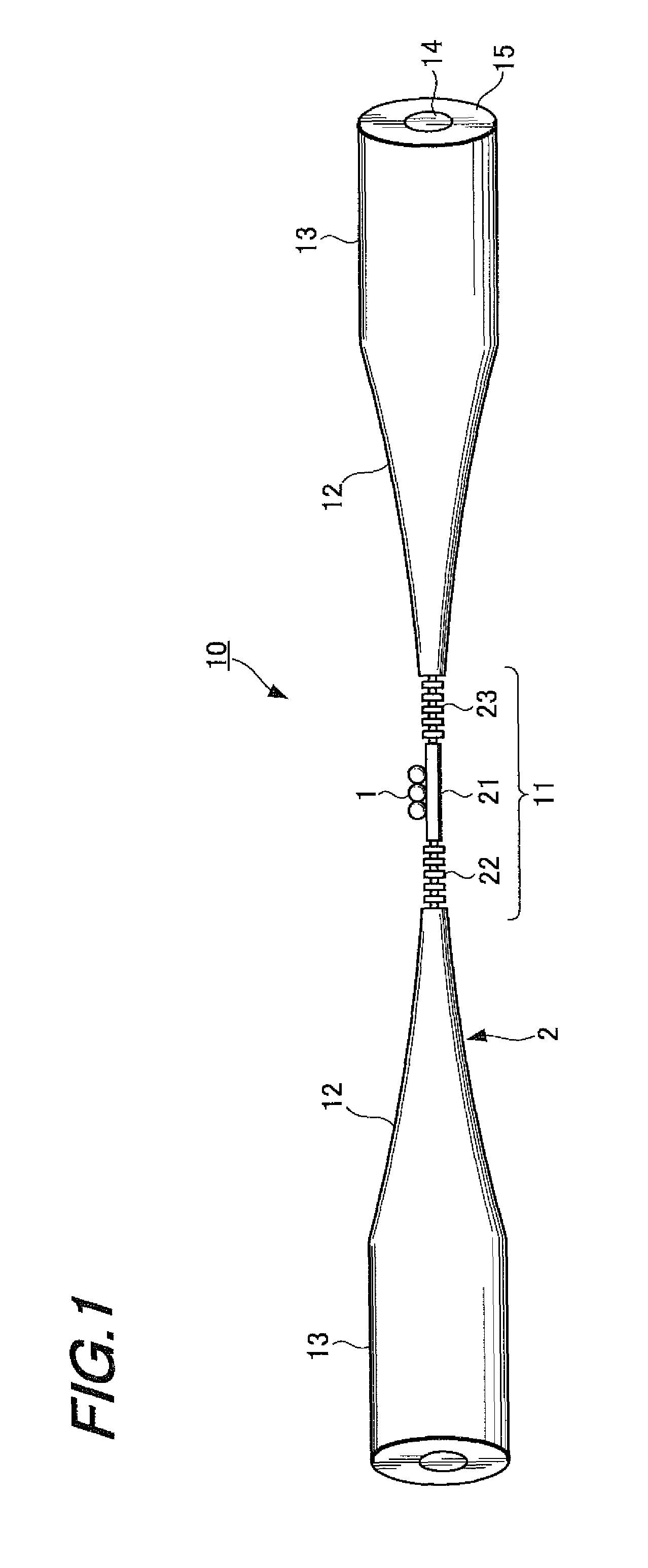
[0040]FIG. 1 schematically shows the configuration of an optical nanofiber resonator according to a first embodiment of the present invention. The optical nanofiber resonator 10 includes light emitters 1 and an optical nanofiber 2 extending in a predetermined direction (i.e., in the right-left direction of FIG. 1).

[0041]The light emitters 1 are arranged on an ultrafine portion (i.e., a resonator portion 11, which is to be described later) of the optical nanofiber 2. The light emitters 1 are composed of atoms, molecules, quantum dots (artificial atoms) or the like. The light emitters 1 are maintained so as to have discrete energy level (i.e., have quantum character), and if the light emitters 1 are laser-excited, a light (photons) having a predetermined wavelength will be emitted by spontaneous emission. Incidentally, the wavelength of the light emitted from the light emitters 1 varies depending on the kind of the light e...

second embodiment

2. Second Embodiment

Configuration of Optical Nanofiber Resonator

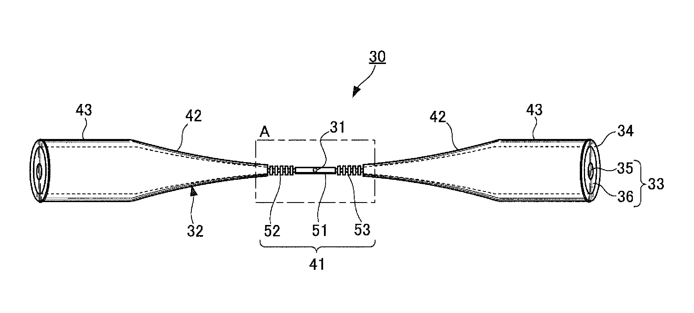
[0111]FIG. 11 schematically shows the configuration of an optical nanofiber resonator according to a second embodiment of the present invention. The optical nanofiber resonator 30 according to the present embodiment includes a light emitter 31 and an optical nanofiber 32. The light emitter 31 may have the same configuration as that of the light emitters 1 of the first embodiment described above.

[0112]The optical nanofiber 32 includes a core portion 33 and a coating layer 34 formed on the core portion 33. The core portion 33 is produced using an optical fiber for communication formed of a material having excellent optical waveguide characteristics (i.e., a material with small photon absorption) such as quartz or the like. Further, the coating layer 34 is formed on a material excellent in workability such as a polymer or the like. Further, in the present embodiment, reflectors are formed in the coating layer 34.

[0113]Furt...

third embodiment

3. Third Embodiment

[0130]In the first and second embodiments, examples are given in which the first reflector and the second reflector are configured by forming a recessed and projected pattern, however the present invention is not limited thereto. Instead of forming a recessed and projected pattern in the optical nanofiber, the reflectors may also be configured, for example, by alternately forming two areas having different refractive indexes along the extending direction of the optical nanofiber. In a third embodiment of the present invention, an example of such configuration will be described below.

[0131]FIG. 14 is a view showing the appearance of an area near a resonator portion (i.e., an ultrafine portion) of an optical nanofiber resonator 60 according to the third embodiment of the present invention. The optical nanofiber resonator 60 according to the present embodiment includes a light emitter 61 and an optical nanofiber 62.

[0132]A resonator portion 71 of the optical nanofibe...


PUM


Abstract

To provide an optical nanofiber resonator having an optical waveguide whose diameter is equal to or smaller than the wavelength of a propagation light, a light emitter disposed at a predetermined position of the optical waveguide, and a first reflector and a second reflector formed in the optical waveguide with the light emitter interposed therebetween, wherein at least one of the first reflector and the second reflector transmits a part of the propagation light. With such a configuration, the channeling efficiency of the light emitted from the light emitter and the propagation mode of the optical waveguide is dramatically improved.

Description

BACKGROUND OF THE INVENTION[0001]1. Field of the Invention[0002]The present invention relates to an optical nanofiber resonator adapted to generate photons and emit the generated photons.[0003]2. Description of the Related Art[0004]Recently, with increase in information communication traffic, there is a desire to develop a new technology capable of dramatically promoting high-level security guarantee technology and high-speed communication technology. As a communication technology capable of solving the problems, quantum information communication technology is being actively studied and developed around the world.[0005]The quantum information communication technology is a communication technology for generating photons (quanta) and manipulating the generated photons, and is a new communication technology to which quantum mechanics principle is directly applied. To be specific, the quantum information communication technology is a technology for performing information communication w...

Claims


Application Information

Patent Timeline
Patent Type & Authority Patents(United States)
IPC IPC(8): G02B6/34G02B6/00G02B6/12G02B6/10H01S3/00H01S3/30
CPCG02B6/0229G02B6/107G02B6/29356G02B6/4287G02B6/4291G02B6/29319
Inventor HAKUTA, KOHZOPHAM, KIEN LE
Owner UNIVERSITY OF ELECTRO-COMMUNICATIONS
Why Eureka
Try Eureka