Coaxial connector

a technology of coaxial connectors and connectors, applied in the field of coaxial connectors, can solve the problems of insufficient accommodation of communication devices for receiving as many as more, and achieve the effect of avoiding interference and less coaxial connectors needed to be installed in communication devices

Active Publication Date: 2018-10-11
GRAND TEK TECH
View PDF0 Cites 2 Cited by
  • Summary
  • Abstract
  • Description
  • Claims
  • Application Information

AI Technical Summary

Benefits of technology

[0013]In summary, the coaxial connector of the present invention applies a first conducting element to receive a multi-frequency signal from a multi-frequency transmission element, and applies a multi-frequency dividing circuit to divide the multi-frequency signal to a plurality of different frequency signals such that the different frequency signals are respectively transmitted to the first coaxial cable and the second coaxial cable of a second conducting element. Furthermore, a first frequency contacting end to which a first RF element is connected and a second frequency contacting end to which a second RF element is connected are respectively connected on one end of the first coaxial cable and one end of the second coaxial cable. Accordingly, two RF elements with two different frequency bands can use only one coaxial connector to connect to a transmission element. Therefore, the amount that the coaxial connectors needed to be installed in a communication device is less. It therefore avoids the interference among / between the coaxial connectors.

Problems solved by technology

In view of the above, one drawback of the conventional coaxial connector in a prior art is that a casing of communication device has insufficient accommodation for receiving as many amount as more than two coaxial connectors.

Method used


Image

  • Coaxial connector
  • Coaxial connector
  • Coaxial connector

Examples


Embodiment Construction

[0018]The preferred embodiments of the present invention are described in detail below with reference to FIG. 1 to FIG. 4. The description is used for explaining the embodiments of the present invention only, but not for limiting the scope of the claims.

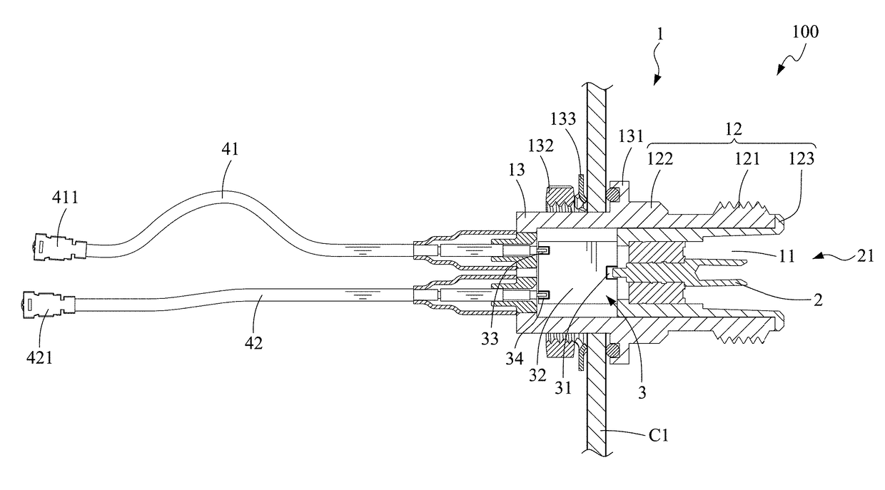
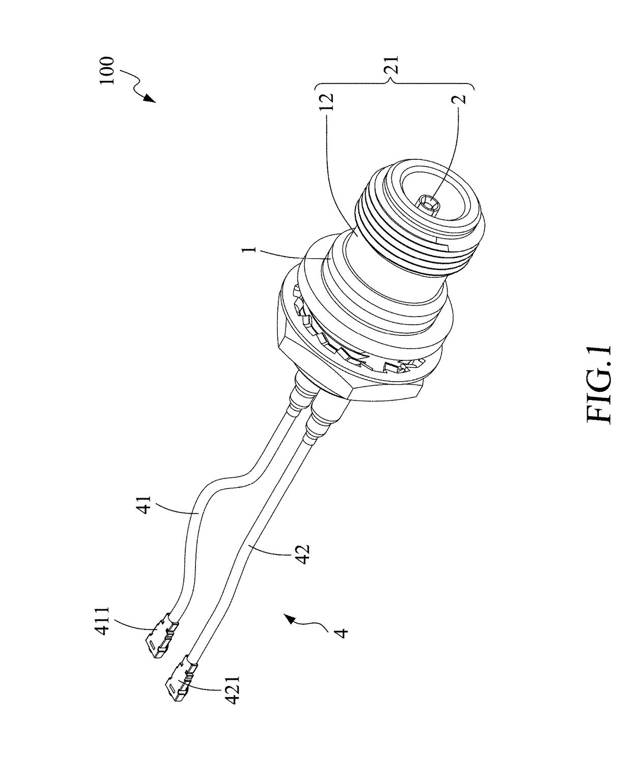
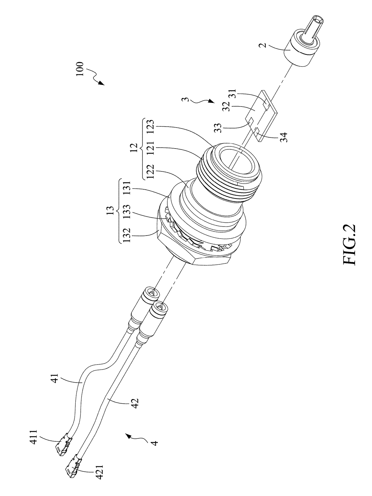
[0019]As shown in FIG. 1 to FIG. 3, a coaxial connector 100 according to one embodiment of the present invention includes: a sleeve element 1, a first conducting element 2, a frequency dividing element 3 and a second conducting element 4. As shown in FIG. 4, one end of the coaxial connector 100 is connected to a multi-frequency transmission element A, and the other end is installed on a casing C1 of a communication device C in a manner that signals are branched to connect to a first RF element C21 and a second RF element C22 on a PCB C2 of the communication device C. However, the present invention is not limited to this and the coaxial connector 100 may be applied to connect between any electronic communication components such as coa...


PUM


Abstract

A coaxial connector of the present invention applies a first conducting element to receive a multi-frequency signal from a multi-frequency transmission element, and applies a multi-frequency dividing circuit to divide the multi-frequency signal to a plurality of different frequency signals such that the different frequency signals are respectively transmitted to the first coaxial cable and the second coaxial cable of a second conducting element. Furthermore, a first frequency contacting end to which a first RF element is connected and a second frequency contacting end to which a second RF element is connected are respectively connected on one end of the first coaxial cable and one end of the second coaxial cable. Accordingly, two RF elements with two different frequency bands can use only one coaxial connector to connect to a transmission element.

Description

FIELD OF THE INVENTION[0001]The present invention relates to a connector, and more particularly relates to a coaxial connector able to perform a frequency dividing operation.BACKGROUND OF THE INVENTION[0002]With the development of the Internet, communication devices, such as switches, modems and routers, have been wildly developing. Due to a large amount of signal transmission, a communication device usually configured with a plurality of board-type RF components on a circuit board to receive signals having respective different frequencies on one frequency band and then to add the signals together so as to increase the signal transmitting amount on one frequency band. However, the board-type RF component on the circuit board is an electronic component with small size such that it is with comparatively poor signal quality. Therefore, an extra transmission component such as a coaxial cable or an antenna is required to externally connect to the board-type RF component for strengthening...

Claims


Application Information

Patent Timeline
Patent Type & Authority Applications(United States)
IPC IPC(8): H01R9/05H01R24/50H01P5/02
CPCH01R9/0521H01R24/50H01R9/0503H01P5/026H01R2103/00H01R24/42H01R24/52H01P5/12
Inventor SHEN, KUNG-YULEE, TA-LUN
Owner GRAND TEK TECH
Why Eureka
Try Eureka