Puncture Repair Liquid Holding Container
- Summary
- Abstract
- Description
- Claims
- Application Information
AI Technical Summary
Benefits of technology
Problems solved by technology
Method used
Image
Examples
Embodiment Construction
[0017]A configuration of the present technology is described in detail below while referring to the attached drawings.
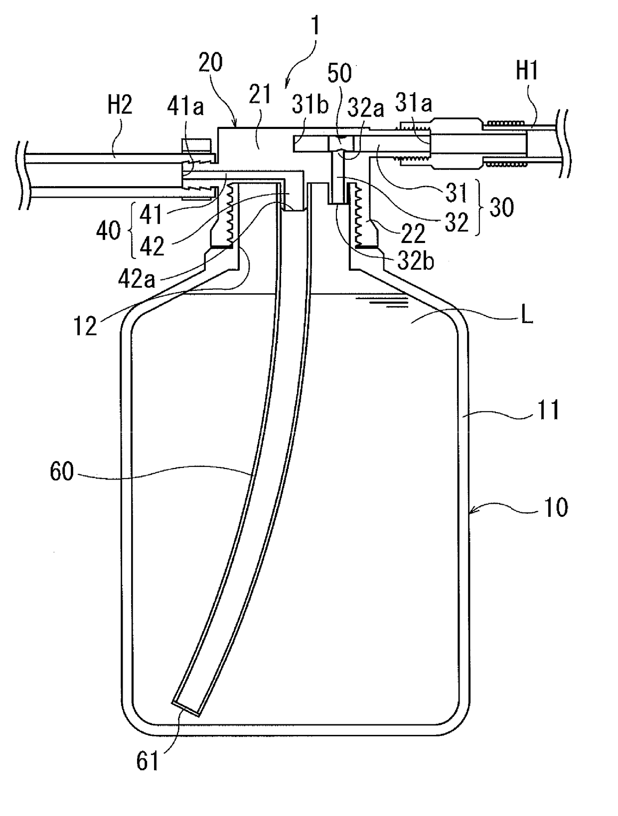
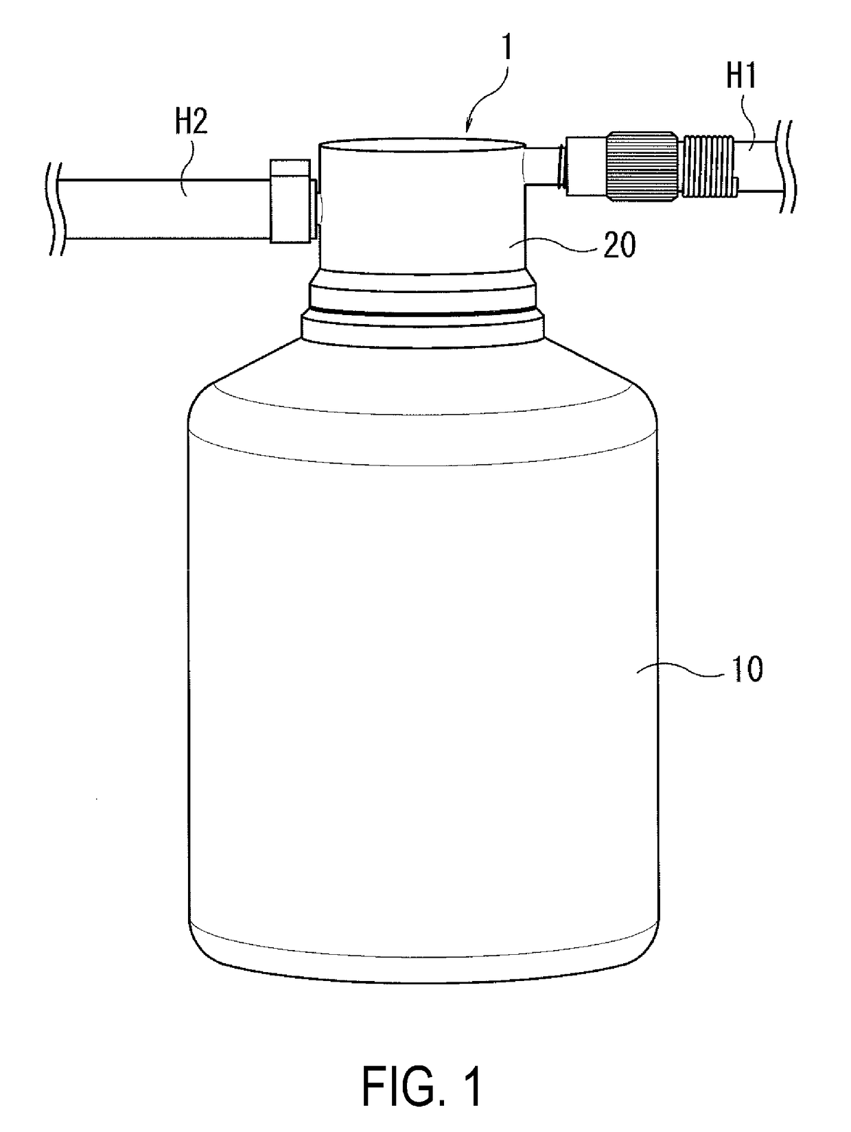
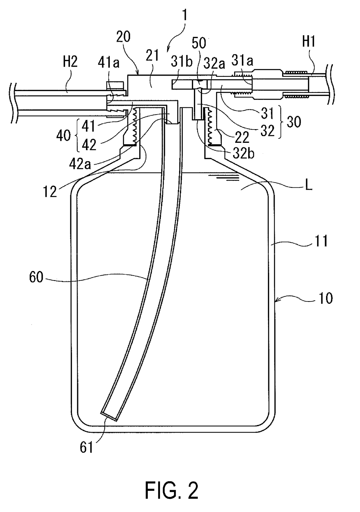
[0018]As illustrated in FIGS. 1 and 2, a puncture repair liquid holding container 1 of the present technology (hereinafter, referred to as “container 1”) is configured from a container main body 10 and a cap 20. Note that FIGS. 1 and 2 illustrate a hose H1 for connecting the container 1 with a high pressure air feeding device, and a hose H2 for the container 1 with a tire, but the structure of the hoses H1, H2 is not particularly limited in the present technology, and therefore, a detailed description will be omitted.
[0019]As illustrated in FIGS. 1 and 2, the container main body 10 has an essentially cylindrical shaped holding portion 11 that holds puncture repair liquid L (hereinafter, referred to as “repair liquid L”) containing rubber latex, and a cylindrical opening portion 12 positioned on an upper side of the holding portion 11 when the container main body 10 i...
PUM
| Property | Measurement | Unit |
|---|---|---|
| Elongation at break | aaaaa | aaaaa |
| Elongation at break | aaaaa | aaaaa |
| Internal pressure | aaaaa | aaaaa |
Abstract
Description
Claims
Application Information
 - R&D
- Intellectual Property
- Life Sciences
- Materials
- Tech Scout
- Unparalleled Data Quality
- Higher Quality Content
- 60% Fewer Hallucinations
Browse by: Latest US Patents, China's latest patents, Technical Efficacy Thesaurus, Application Domain, Technology Topic, Popular Technical Reports.
© 2025 PatSnap. All rights reserved.Legal|Privacy policy|Modern Slavery Act Transparency Statement|Sitemap|About US| Contact US: help@patsnap.com


