
Image Forming system and Control Method for Image Forming System

Active Publication Date: 2018-10-18
KONICA MINOLTA INC
View PDF0 Cites 1 Cited by
  • Summary
  • Abstract
  • Description
  • Claims
  • Application Information

AI Technical Summary

Benefits of technology

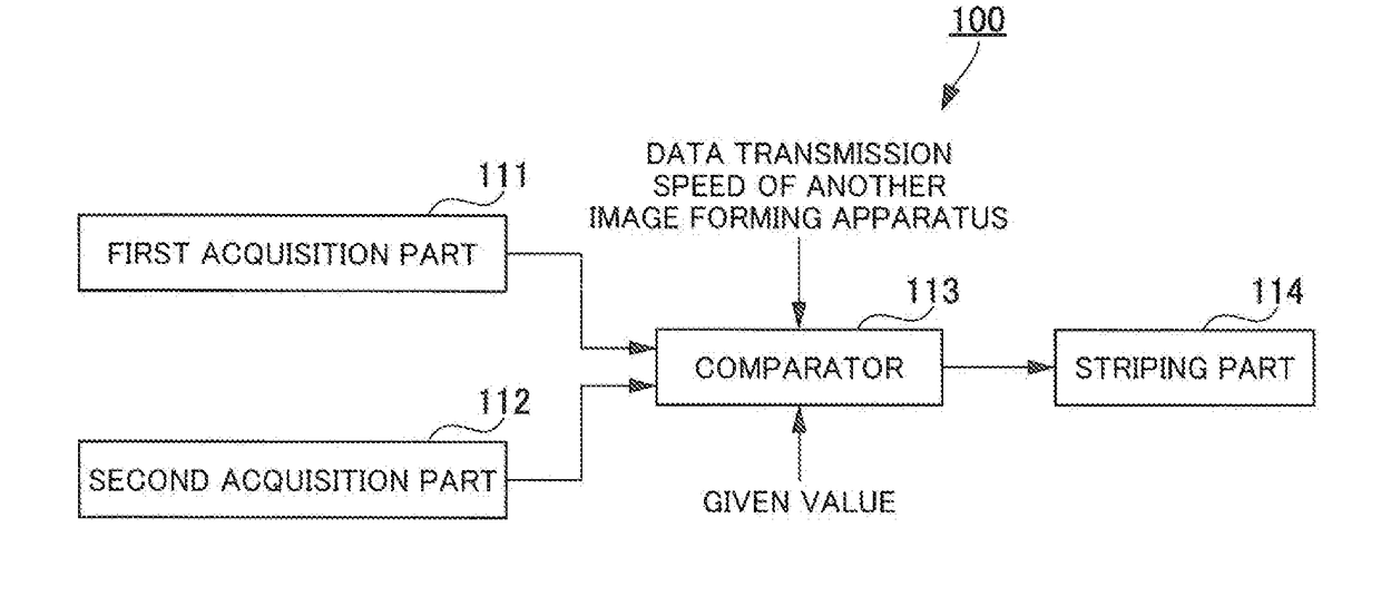
The present invention provides an image forming system and method that can increase printing speed without user intervention, even if the speed of data transmission to the storage does not meet the allowable speed. This is achieved by comparing the speed of data transmission to the storage of another image forming apparatus on the same network, and using the storage of another apparatus if both speeds are higher than the given value. This avoids the need for additional storage and ensures efficient use of available resources.

Problems solved by technology

Specifically, each time the speed of data transmission to the storage does not meet the allowable speed, the user must install a storage manually.
Thus, the related art is less user-friendly because the user must intervene whenever the speed of data transmission to the storage does not meet the allowable speed.

Method used


Image

  • Image Forming system and Control Method for Image Forming System
  • Image Forming system and Control Method for Image Forming System
  • Image Forming system and Control Method for Image Forming System

Examples


example 1

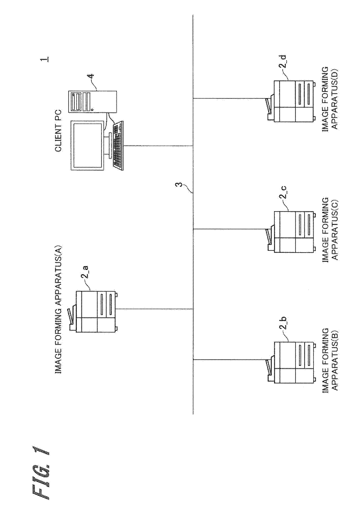
[0093]Example 1 is an example of operation in the case that the speed of data transmission to the storage does not meet the specified printing speed due to combined operation of printing and scanning in the image forming apparatus (A)2_a.

[0094]In the image forming apparatus (A)2_a, usually the speed of access to the HDD91_a is 200 [MB / s], which exceeds the specified transmission speed (access speed) of 133.3 [MB / s] and thus meets the specified printing speed. However, in the case of combined operation, the speed of access to the HDD91_a declines due to excessive access to the HDD91_a. If the speed of access to the HDD91_a goes down to 100 [MB / s] due to combined operation, the speed is lower than the specified transmission speed of 133.3 [MB / s] and does not meet the specified printing speed.

[0095]For this reason, in Example 1, in combined operation, the system checks whether or not the speed of access to the HDD91_b of the image forming apparatus (B)2_b and the data transmission spe...

example 2

[0101]Example 2 is an example of operation in the case that the power of the image forming apparatus (B)2_b having striped image data is turned off.

[0102]Here, it is assumed that the speed of access to the HDD91_b does not meet the specified reading speed for the image reader 30 during scanning operation of the image forming apparatus (A)2_a. In this case, through processing in Example 1, the image data is stored in the HDD91_a of the image forming apparatus (A)2_a and the HDD91_b of the image forming apparatus (B)2_b by striping.

[0103]In Example 2, after the image data is stored in the HDD91_b of the image forming apparatus (B)2_b by striping, the storage into which the image data in the HDD91_b is stored (storage destination) is changed when the power of the image forming apparatus (B)2_b is turned off. Specifically, as shown in FIG. 7, the image data in the HDD91_b is transmitted to an image forming apparatus other than the image forming apparatus (B)2_b, for example, the HDD91_c...

example 3

[0109]Example 3 is an example of operation in the case that the power of the image forming apparatus (B)2_b having striped image data is off.

[0110]In Example 3 as well, as in Example 2, it is assumed that during scanning operation of the image forming apparatus (A)2_a, image data is stored in the HDD91_a of the image forming apparatus (A)2_a and the HDD91_b of the image forming apparatus (B)2_b by striping.

[0111]After image data is stored in the HDD91_b of the image forming apparatus (B)2_b by striping, when the image forming apparatus (A)2_a tries to read the image data stored in the HDD91_b, if the sub power supply of the image forming apparatus (B)2_b is off, the image forming apparatus (A)2_a cannot read the image data from the HDD91_b and cannot use the image data.

[0112]Therefore, in Example 3, as shown in FIG. 9, the image forming apparatus (A)2_a, going to use the image data, remotely starts only the function to access the HDD91_b of the image forming apparatus (B)2_b, by sen...


PUM


Abstract

An image forming system which suppresses the decline in printing speed without user intervention when the speed of data transmission to a storage does not meet an allowable speed, and a control method for the system. A first acquisition part acquires the speed of data transmission to the storage of each of plural image forming apparatuses and a second acquisition part acquires the data transmission speed between image forming apparatuses. When the speed of data transmission to a given image forming apparatus among the apparatuses is lower than a specified value, if the speed of data transmission to the storage of another image forming apparatus and the data transmission speed between image forming apparatuses are both higher than a given value, a striping part performs striping to distribute and store data into the storage of the given image forming apparatus and the storage of the other image forming apparatus.

Description

CROSS-REFERENCE TO RELATED APPLICATIONS[0001]The entire disclosure of Japanese Patent Application No. 2017-81428, filed on Apr. 17, 2017, is incorporated herein by reference in its entirety.BACKGROUND[0002]An image forming apparatus has a storage such as an HDD (Hard Disk Drive) or SSD (Solid State Drive) to perform a printing process or scanning process through the storage. Therefore, if the storage is excessively accessed because of combined operation of printing and scanning or another reason, the speed of data transmission to the storage declines and as a consequence, the printing speed declines.[0003]One technique to solve the above problem is that if the speed of data transmission to the storage does not meet the allowable speed, a warning is given to the user and upon receipt of the warning the user manually installs an additional storage to increase the speed of data transmission to the storage by striping with the additional storage (for example, see Patent Literature 1).Te...

Claims


Application Information

Patent Timeline
IPC IPC(8): G06F3/12G03G15/00H04N1/00H04L12/26
CPCG06F3/122G03G15/5075H04N1/0001G06F3/1295G06F3/1215G06F3/1205H04N1/0009H04L43/16G06F3/1204H04L43/0888G03G15/5083G03G2215/00021G06F3/1211G06F3/1261G06F3/1291
Inventor IKUTA, MASAYA
Owner KONICA MINOLTA INC
Learn More