

Solid-state image pickup device and camera including the same
- Summary
- Abstract
- Description
- Claims
- Application Information
AI Technical Summary
Benefits of technology
Problems solved by technology
Method used
Image

Examples
first embodiment
[0043] Hereinafter, with reference to figures, a first embodiment of the present invention will be described.
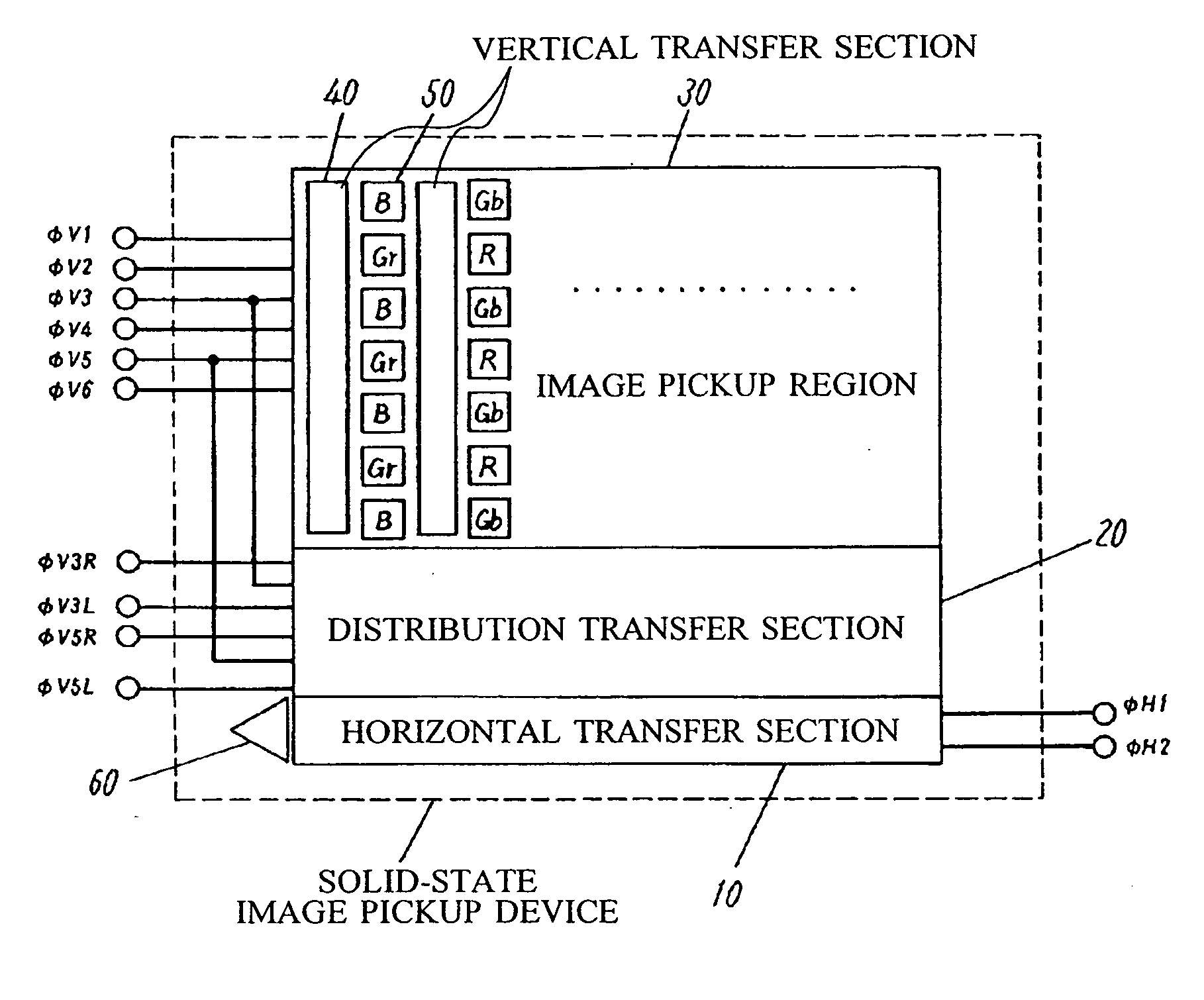
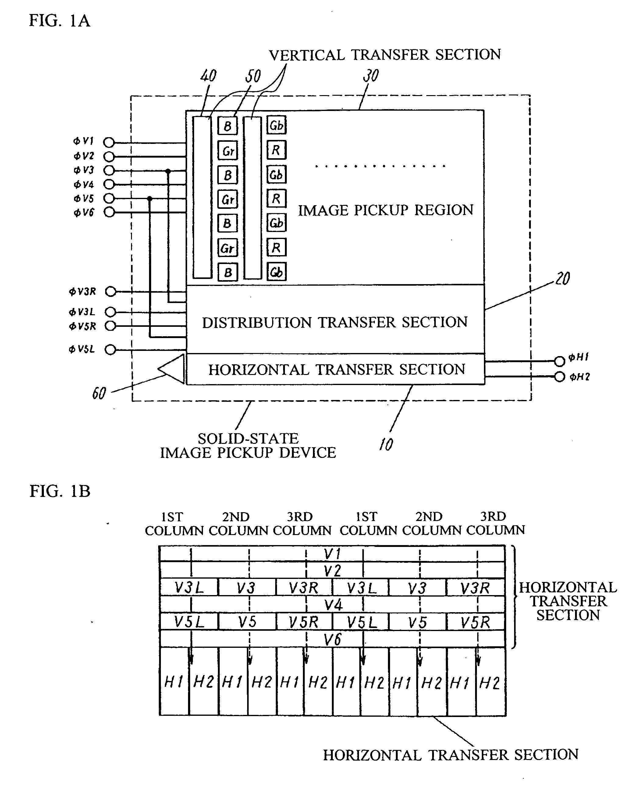
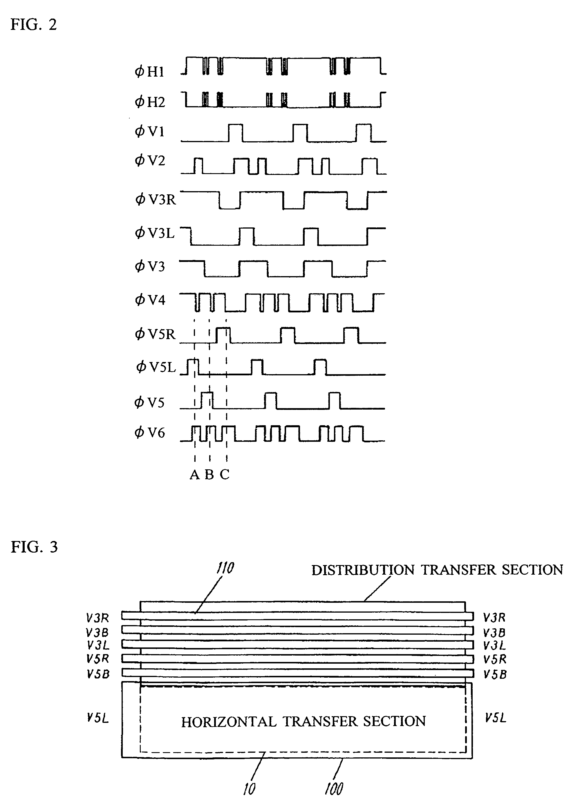
[0044]FIG. 1A is a diagram illustrating a solid-state image pickup device according to the first embodiment of the present invention. FIG. 1B is a diagram illustrating an arrangement of gates in a distribution transfer section.
[0045] In FIG. 1A, light entering an image pickup region is photoelectric-converted by a photo-detecting section 50 and a signal charge is generated. The signal charge is read out by a readout transistor or the like (not shown) to a vertical transfer section 40. Thereafter, the signal charge is transferred by the vertical transfer section 40 and reaches a horizontal transfer section 10.
[0046] The solid-state image pickup device according to the first embodiment comprises a plurality of photo-detecting sections 50, which are disposed in a two-dimensional manner corresponding to pixels and in each of which any of filters of three colors such as red (R)...
second embodiment
[0087] Next, with reference to figures, a camera, including the solid-state image pickup device, according to a second embodiment of the present invention will be described.
[0088]FIG. 6 is a block diagram illustrating the camera, including the solid-state image pickup device, according to the second embodiment.
[0089] In FIG. 6, the camera according to the second embodiment comprises a lens 1000, the solid-state image pickup device 1010 according to the above-described first embodiment, a driving circuit 1020, a signal processing section 1030, an external interface 1040.
[0090] In the camera, light which passes through the lens 1000 enters the solid-state image pickup device 1010. The signal processing section 1030 controls the driving circuit 1020 to drive the solid-state image pickup device 1010, loads output signals from the solid-state image pickup device 1010, and performs various processes on the loaded output signals. The signals processed by the signal processing section 10...
PUM
 Abstract
Description
Claims
Application Information