

Mechanically actuated leveling valve mechanism
a technology of mechanical action and leveling valve, which is applied in the direction of valve gearing, valve operating means/release devices, transportation and packaging, etc., can solve the problems of unstable drive state and overshooting of roll angl
- Summary
- Abstract
- Description
- Claims
- Application Information
AI Technical Summary
Benefits of technology
Problems solved by technology
Method used
Image

Examples
Embodiment Construction
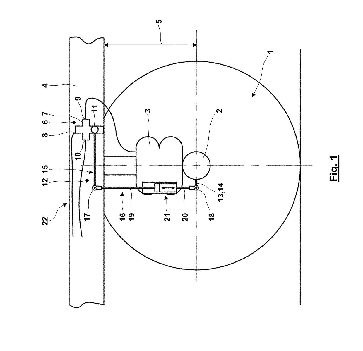
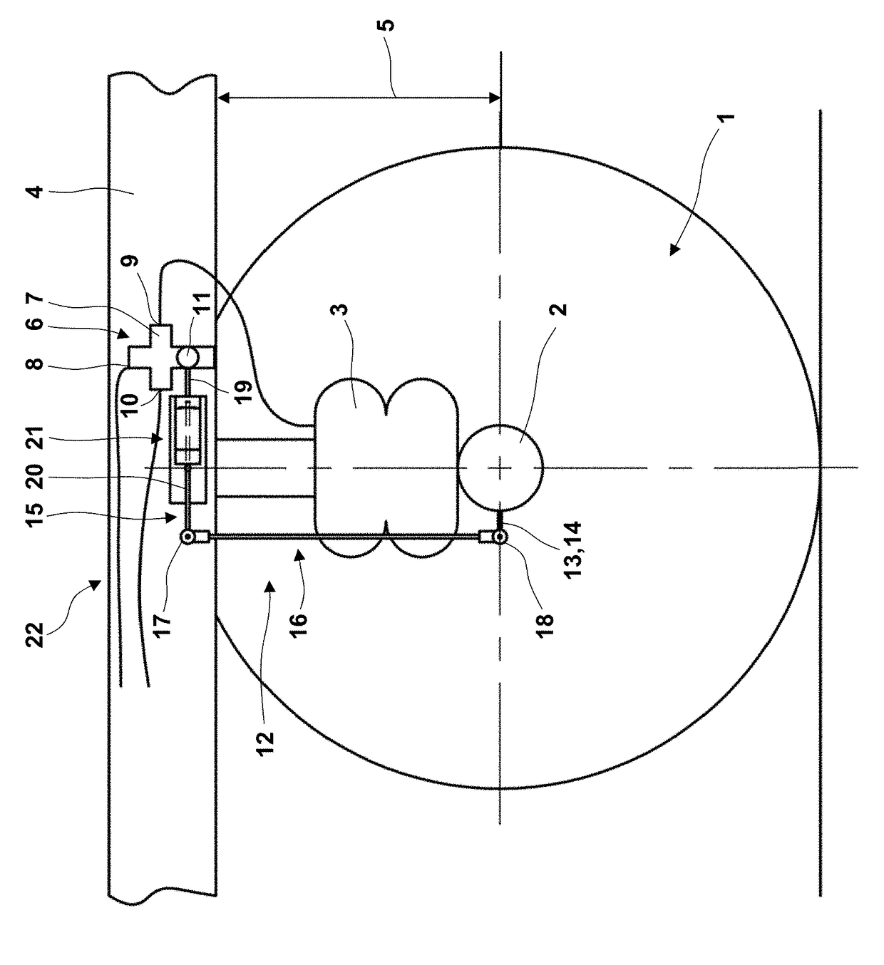
[0032]The present invention proposes, differently to the proposal according to document US 2012 / 0146307 A1, not to move a housing of the level control valve device relative to the vehicle frame but, rather than that, to fix it to the vehicle frame. According to the invention, at a fixed position and orientation of a housing of the mechanically actuated level control valve device, a reference position of the level control valve device can be changed. A change of the reference position may be induced, for example, by a manual setting by the user, for example for lifting or lowering the vehicle body at a ramp. It is also possible, however, that the reference position is changed during driving operation within an electronic control. The reference position correlates with a blocking position of the level control valve device, in which there is no level change. The reference position is given by a relative position of the components of the level control valve device which take part in aer...
PUM
 Abstract
Description
Claims
Application Information