Detection apparatus and inlet structure thereof

a technology of detection apparatus and inlet structure, which is applied in the direction of separation process, instruments, laboratory glassware, etc., can solve the problems of fluid behavior, increased production cost of detection apparatus, and difficulty in being guided into the inl

Inactive Publication Date: 2018-10-25
SKYLA CORP HSINCHU SCI PARK BRANCH
View PDF1 Cites 3 Cited by
  • Summary
  • Abstract
  • Description
  • Claims
  • Application Information

AI Technical Summary

Benefits of technology

[0005]The invention provides an inlet structure capable of destroying a surface tension of a fluid to cause the fluid to flow into a microchannel by a capillary action.

Problems solved by technology

In a conventional detection apparatus, when a fluid is dropped into an inlet of the detection apparatus, the behavior of the fluid is influenced by the surface tension easily and has difficulty of being guided into the inlet.
In this way, production cost of the detection apparatus is increased.

Method used


Image

  • Detection apparatus and inlet structure thereof
  • Detection apparatus and inlet structure thereof
  • Detection apparatus and inlet structure thereof

Examples


Embodiment Construction

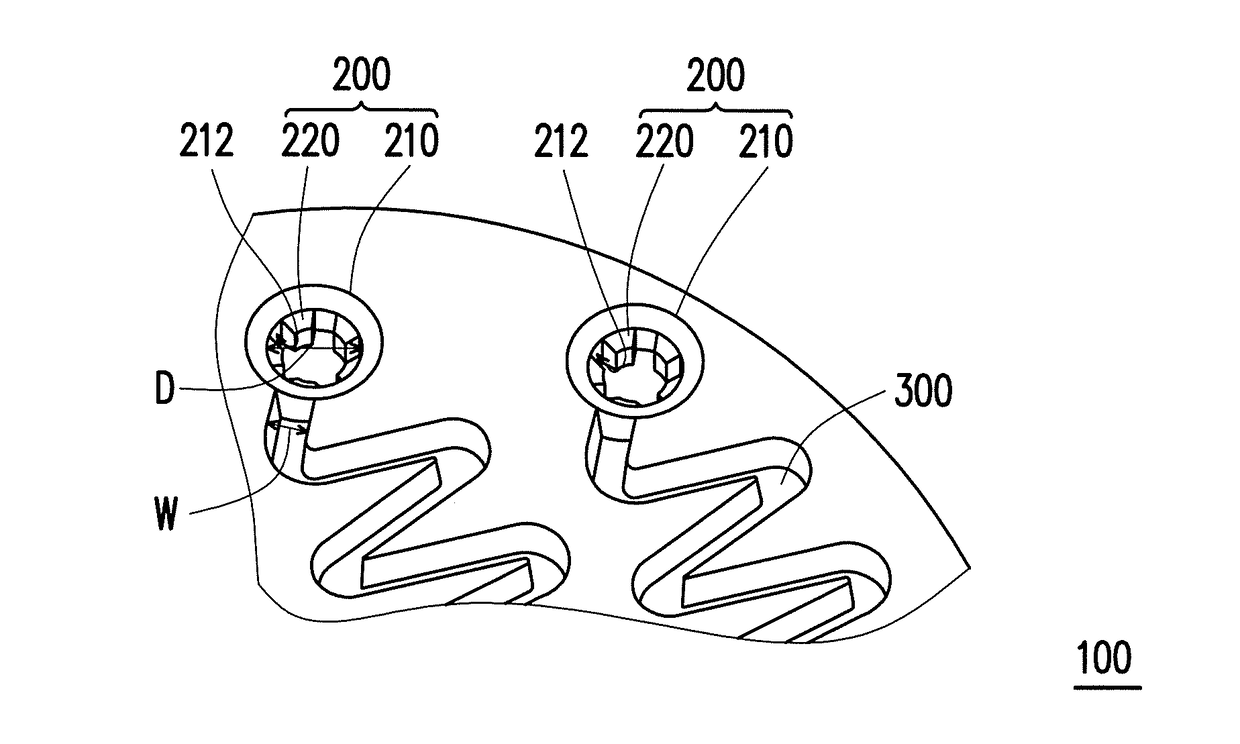
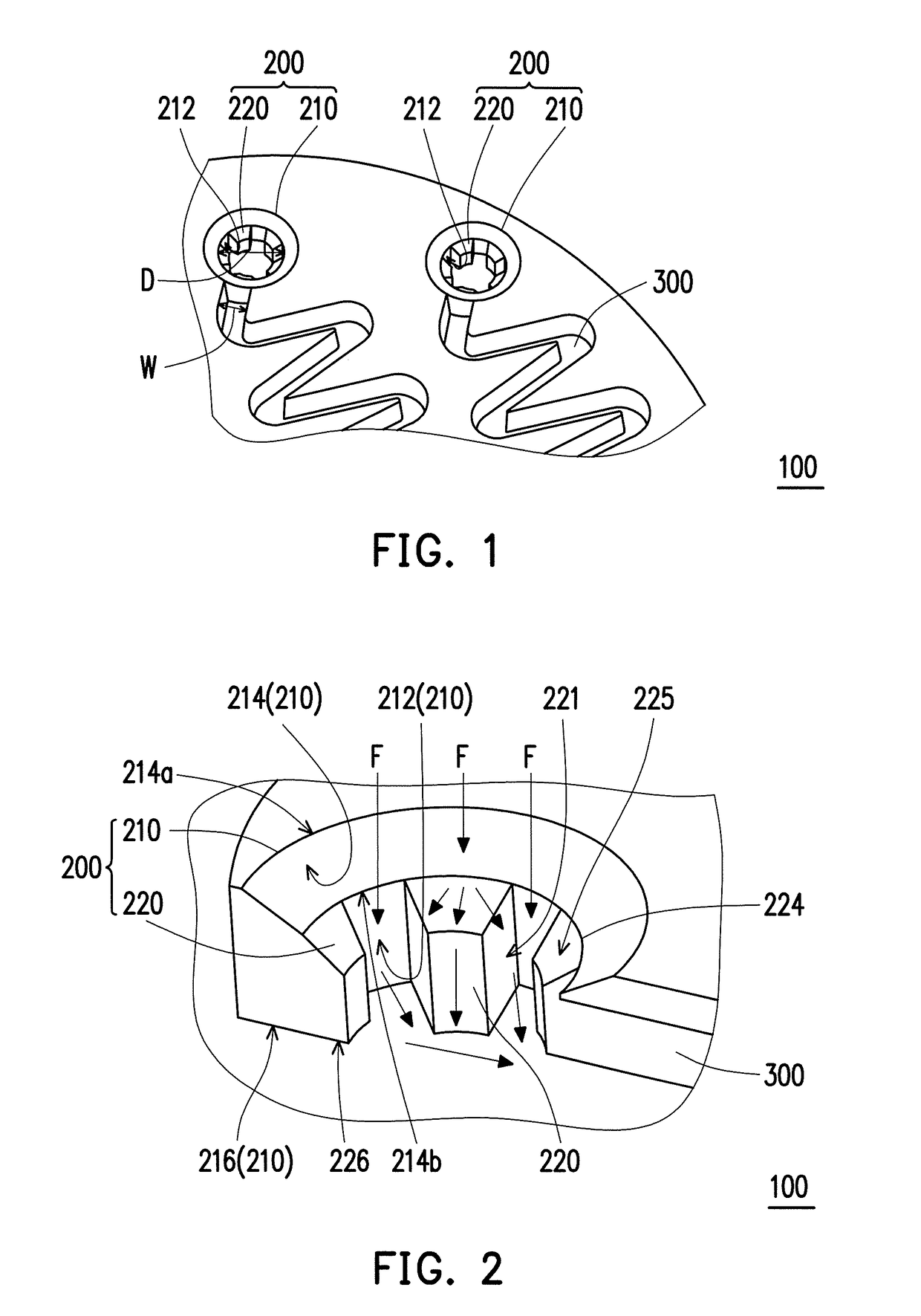
[0025]FIG. 1 is a partial top view of a detection apparatus according to an embodiment of the invention. FIG. 2 is a partial perspective cross-sectional view of the detection apparatus depicted in FIG. 1. Referring to both FIG. 1 and FIG. 2, a detection apparatus 100 of the present embodiment includes at least one inlet structure 200 (which only two are schematically illustrated in FIG. 1) and at least one microchannel 300 (which only two are schematically illustrated in FIG. 1). Each of the inlet structures 200 is adapted to be respectively connected to each of the micro channels 300.

[0026]To be specific, each of the inlet structures 200 of the detection apparatus 100 of the present embodiment includes an inlet portion 210 and at least one micro structures 220 (which five are schematically illustrated in FIG. 1). The inlet portion 210 has an inner surface 212, and the micro structure 220 is disposed in the inlet portion 210 and connected to the inner surface 212. Particularly, when...


PUM


Abstract

An inlet structure is adapted to be connected to a microchannel. The inlet structure includes an inlet portion and at least one micro structure. The inlet portion contains an inner surface. The micro structure is disposed in the inlet portion and connected to the inner surface. When a fluid is injected into the inlet portion, the micro structure destroys a surface tension of the fluid to cause the fluid to flow into the microchannel by capillary action.

Description

CROSS-REFERENCE TO RELATED APPLICATION[0001]This application claims the priority benefit of China application no. 201710256374.3, filed on Apr. 19, 2017. The entirety of the above-mentioned patent application is hereby incorporated by reference herein and made a part of this specification.BACKGROUND OF THE INVENTIONField of the Invention[0002]The invention is directed to a detection apparatus and an inlet structure thereof and more particularly, to an inlet structure capable of destroying a surface tension of a fluid and a detection apparatus applying the inlet structure.Description of Related Art[0003]To satisfy demands of emphasis on preventive medicine, early diagnosis and early treatment in medical treatment, demands on automated testing environment, point of care (POC) or near patient testing and molecular diagnosis have increased. Currently, most of the blood samples are still separated in the centrifuge, and fluids to be tested after the separation are further taken therefrom...

Claims


Application Information

Patent Timeline
Patent Type & Authority Applications(United States)
IPC IPC(8): B01L3/00B81B1/00
CPCB01L3/5027A61B5/1405A61B10/0045B81B1/00B01L3/502715B01L2200/10B01L2400/0406G01N33/50B01L3/50273B01L3/502746B01L2200/027B01L2300/0858B01L2400/084B01L2400/086B81B7/0061B81B2201/058
Inventor WEI, CHIA-CHUNCHEN, HUNG-WEI
Owner SKYLA CORP HSINCHU SCI PARK BRANCH
Why Eureka
Try Eureka