Central shaft for bridge plug, bridge plug and setting method for the same

a technology of central shaft and bridge plug, which is applied in the direction of earthwork drilling, sealing/packing, and well accessories, etc., can solve the problems of affecting the normal use of bridge plugs, affecting the period and cost of construction, and high cost and difficulty of recovery or plug drilling, so as to increase the overall strength of the central shaft

Active Publication Date: 2018-10-25
CHEN AIMIN
View PDF9 Cites 12 Cited by
  • Summary
  • Abstract
  • Description
  • Claims
  • Application Information

AI Technical Summary

Benefits of technology

[0024]In the central shaft for the bridge plug provided by the present disclosure, the setting mandrel not only functions as a release sub as in the existing bridge plug, but can also function in a manner so that, after the bridge plug is set on the inner wall of a sleeve (or the wall of a well if necessary) and the setting tubular shaft is in the setting state, the setting mandrel can be brought (by a bridge plug running tool) to move and thus be disconnected from the downstream-end support of the bridge plug. After the setting mandrel is withdrawn from the central hole of the setting tubular shaft, the downstream-end support of the bridge plug drops to the bottom of the well and the central hole of the setting tubular shaft forms an internal fluid channel of the bridge plug. Since the strength of the material of the setting mandrel is higher than the strength of the degradable material or corrodible material and the strength of the material of the setting tubular shaft is not lower than the strength of the degradable material or corrodible material, the presence of the setting mandrel (and even the setting tubular shaft) increases the overall strength of the central shaft of the bridge plug. Under the premise that the overall strength of the central shaft of the bridge plug can meet the requirements for setting of the bridge plug, the wall thickness of the setting tubular shaft can be made very thin, and accordingly the dimension of the central hole of the setting tubular shaft, i.e. the inner diameter of the internal fluid channel of the bridge plug, can be made larger than the existing bridge plug.

Problems solved by technology

Firstly, the normal use of the bridge plug is affected by the issue of midway setting, which easily occurs in the process of running the bridge plug due to free movement of a bridge plug running tool and release setting of the bridge plug.
Once the midway setting occurs, recovery or drilling removal treatment needs to be carried out, which influences the period and costs of construction.
Secondly, recovery or plug drilling is high in cost and difficulty, restrictive conditions (e.g., settled sand, dropping objects, and well wall scale) in a shaft during plug drilling lead to more difficult plug drilling, and the shaft thus needs to be treated in advance through other processes, which leads to the increase in costs of construction, and even complex conditions occurred in the shaft, affecting the normal production of oil and gas wells.
Thirdly, the existing bridge plug is unstable in plugging effect after setting.
The reason for this is that a leaking channel exists between a rubber cylinder of the bridge plug and a well wall, and the bridge plug loses the role of plugging, resulting in unclear directions where a fracturing fluid goes and causing serious waste.
Fourthly, the bridge plug is unreliable in anchoring after setting, and goes down during fracturing, leading to the cancellation of zoning and a serious impact on the quality of zonal fracturing construction.
However, the degradation characteristics of degradable plastics and degradable metal materials are restricted by the environment of their applications, and the strength of the degradable materials is 50% lower than that of carbon steel metal materials, so that this kind of materials cannot be used to manufacture a bridge plug with a large inner diameter.

Method used


Image

  • Central shaft for bridge plug, bridge plug and setting method for the same
  • Central shaft for bridge plug, bridge plug and setting method for the same
  • Central shaft for bridge plug, bridge plug and setting method for the same

Examples


Embodiment Construction

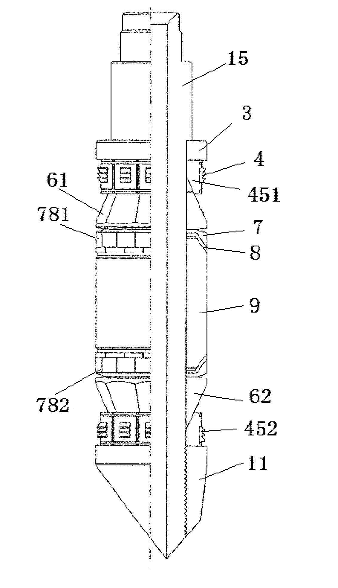
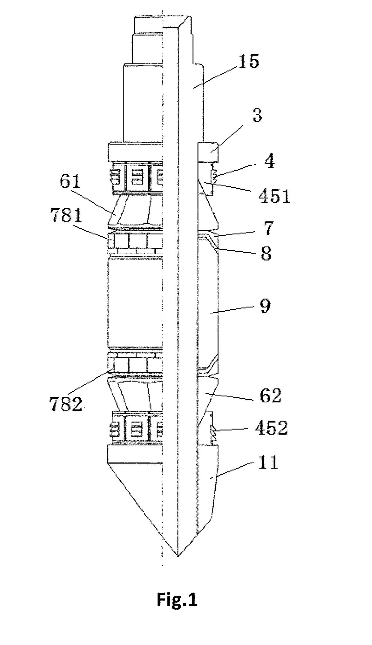
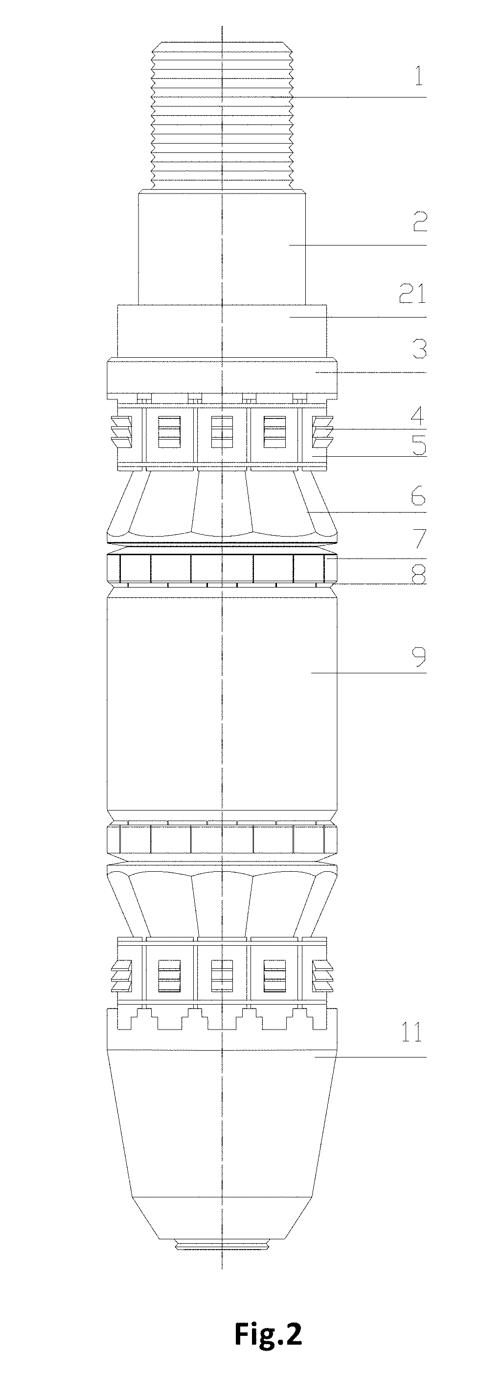
[0049]As shown in FIGS. 2-24, a central shaft for a bridge plug provided by an embodiment of the present disclosure comprises a setting mandrel 1 and a setting tubular shaft 2, wherein

[0050]the setting tubular shaft 2 is provided with a central hole, and includes a squeezing shoulder 21 for squeezing a compression ring (which may also be referred as a pushing disc, a positioning disc, a squeezing ring) 3 of the bridge plug or an upper slip assembly 451 of the bridge plug, and a support trunk 22 for at least supporting the upper slip assembly 451, a reducing support ring (which may also be referred as a reducing sheath) 78, a slip platen (preferably a hollow cone) 6 and an elastic sealing cylinder (preferably a degrading rubber cylinder) 9 of the bridge plug, wherein the elastic sealing cylinder 9 may be formed by splicing a plurality of segments of elastic rings or elastic cylinders;

[0051]the central hole of the setting tubular shaft 2 is sleeved outside the setting mandrel 1 and th...


PUM


Abstract

The present disclosure discloses a central shaft for a bridge plug, a bridge plug and a setting method for the bridge plug, and relates to the technical field of bridge plug. The present disclosure addresses the technical problems existing in the prior art that degradable plastics and degradable metal materials are unable to manufacture a bridge plug with a large inner diameter. The central shaft comprises a setting mandrel and a setting tubular shaft, and the setting tubular shaft includes a squeezing shoulder for squeezing a compression ring or a reducing support ring of the bridge plug, and a support trunk; after the setting mandrel is disconnected from the downstream-end support, the setting mandrel can be withdrawn from the central hole of the setting tubular shaft so that the central hole of the setting tubular shaft forms an internal fluid channel of the bridge plug; and the strength of the material of the setting mandrel is higher than the strength of a degradable material or corrodible material, and the material of the setting tubular shaft is a degradable material or a corrodible material. The bridge plug comprises the central shaft provided in the present invention. The present disclosure is used to enlarge the inner diameter of the bridge plug, and improve the plugging effect, anchoring performance and construction convenience of the bridge plug.

Description

FIELD OF THE INVENTION[0001]The present disclosure relates to the technical field of bridge plug, and in particular to a central shaft for a bridge plug, a bridge plug using the central shaft and a setting method for the bridge plug.BACKGROUND OF THE INVENTION[0002]In the exploration and development of an oilfield, a temporary plugging process is needed to plug a current production zone to facilitate implementation of process measures to other production zones. The temporary plugging is cancelled after the completion of the process, and a flowing channel between the production zone (or zones) and the shaft is established for oil extraction and gas production on oil and gas wells. Although the plugging technology using bridge plugs has been widely applied in the fracturing measure innovation and the processes of development and production, the inventors of the present application have found that at least the following technical problems exist in a bridge plug as shown in FIG. 1 provi...

Claims


Application Information

Patent Timeline
Patent Type & Authority Applications(United States)
IPC IPC(8): E21B33/129E21B33/12E21B33/128E21B33/134E21B29/00E21B23/06
CPCE21B33/1292E21B33/1208E21B33/128E21B33/134E21B29/00E21B23/06
Inventor CHEN, AIMIN
Owner CHEN AIMIN
Why Eureka
Try Eureka