Optical tweezers device

Active Publication Date: 2018-10-25
JTEKT CORP
View PDF0 Cites 0 Cited by
  • Summary
  • Abstract
  • Description
  • Claims
  • Application Information

AI Technical Summary

Benefits of technology

The invention allows for the creation of an image where a particle appears to be moving, even in a device that uses a laser beam to move the stage and focus it.

Problems solved by technology

However, this results in problems that the overall device becomes expensive and a very wide space is necessary to install component devices.
However, if there does not exist any other particle (not to be trapped) around the particle being trapped, it is unknown at all whether the particle being trapped is moving.

Method used


Image

  • Optical tweezers device
  • Optical tweezers device
  • Optical tweezers device

Examples


Embodiment Construction

[0023]An embodiment of the present invention will be hereinafter described on the basis of the drawings

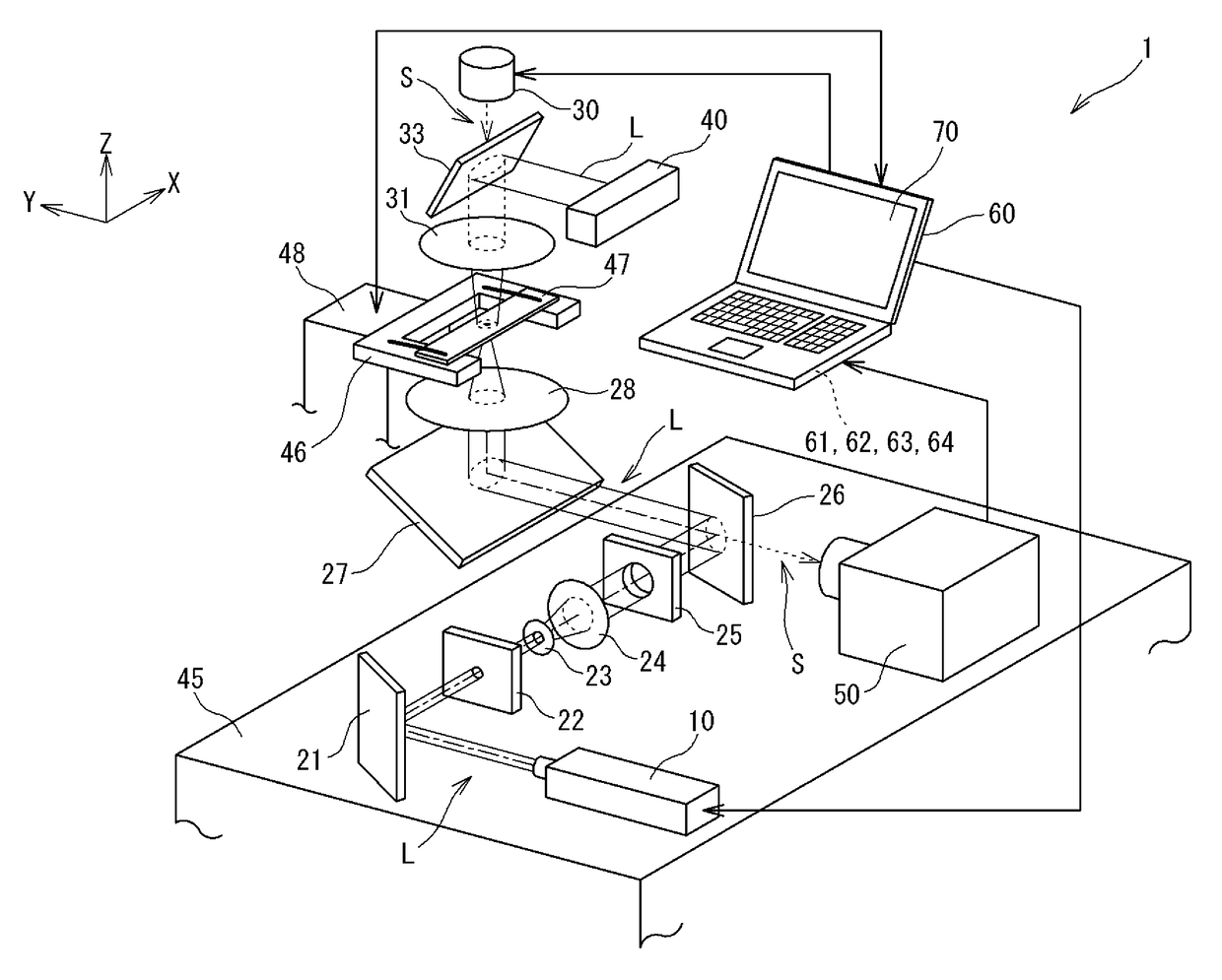
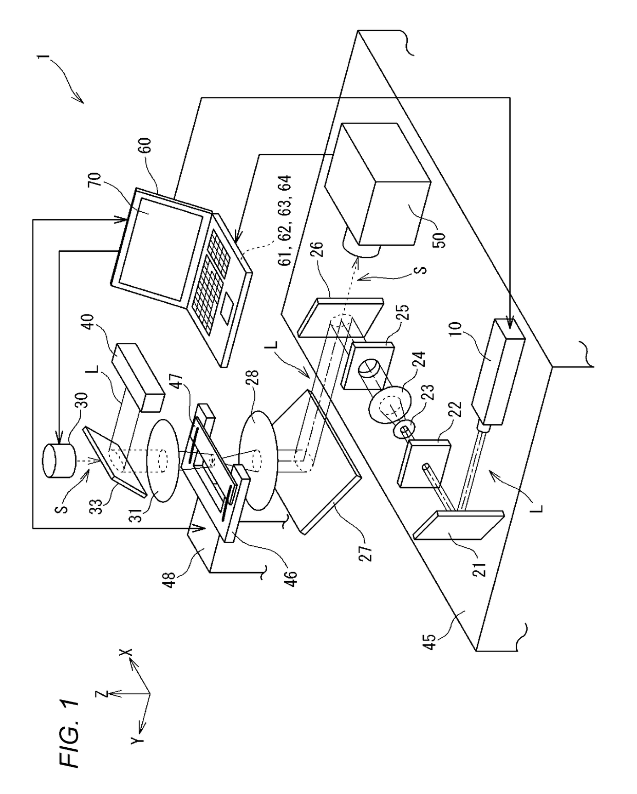
[0024]FIG. 1 is an explanatory diagram for description of the overall configuration of an optical tweezers device 1. The optical tweezers device 1 includes a light source 10 of a laser beam, light guiding means (21-27), a first lens 28, an illumination light source 30, a second lens 31, a mirror (third mirror) 33, a detector 40, a device base 45, a stage 46, a drive means 48, an imaging means 50, and a control means 60.

[0025]As described later, the optical tweezers device 1 is configured in such a manner that the stage 46 can be moved by the drive means 48 with respect to the device base 45 which is fixed to a working floor. And other devices, that is, the light source 10, the lenses 28 and 31, the detector 40, the imaging means 50, etc., are fixed to the device base 45 and are not moved with respect to the device base 45.

[0026]The light source 10 of the laser beam, which is a lase...


PUM


Abstract

An optical tweezers device includes: an acquisition unit which acquires basic movement information indicating a movement of a stage; a conversion unit which converts the movement of the stage indicated by the basic movement information into a movement of a particle being trapped and generates converted movement information indicating the movement of the particle; and a distance calculation unit which determines a distance between the particle being trapped by the laser beam and a focal point of the lens. The conversion unit generates the converted movement information by correcting the movement of the particle using the distance determined by the distance calculation unit.

Description

TECHNICAL FIELD[0001]An aspect of the present invention relates to an optical tweezers device.BACKGROUND ART[0002]The optical tweezers technology is known which is a technology for trapping, for example, a particle measuring about 1 μm and, furthermore, moving it (refer to Patent document 1, for example). According to the optical tweezers technology, a laser beam is focused with a lens and a particle that is brought close to a focusing point is trapped by optical pressure acting on it. The optical tweezers technology makes it possible to continue to trap a particle by, for example, causing the particle to exist in a liquid, producing a refractive index difference between the particle and liquid around it, and directing the total force of optical pressure acting on the particle to the focusing point.[0003]To trap a particle utilizing the optical tweezers technology described above, it is necessary that the particle have transmittivity (transmit the laser beam) and that the refractive...

Claims


Application Information

Patent Timeline
IPC IPC(8): G02B21/32G02B21/26B25J7/00
CPCG02B21/32G02B21/26B25J7/00
Inventor NANRI, KOTASAITO, TOSHIYUKISUZUKI, KENSUKE
Owner JTEKT CORP
Why Eureka
Try Eureka