Image Processing Apparatus and Its Method

a processing apparatus and image technology, applied in the field of image processing, can solve the problems of suppressing the reduction in the quality of visible images, unable to achieve the effect of trapping process, and insufficiently obtaining color information about spot colors in image data

Inactive Publication Date: 2008-11-06
CANON KK
View PDF12 Cites 6 Cited by
  • Summary
  • Abstract
  • Description
  • Claims
  • Application Information

AI Technical Summary

Benefits of technology

[0024]The first aspect of the present invention discloses an image processing apparatus for generating image data for forming a visible image by overlaying a plurality of colors including a spot color, comprising: an input section, arranged to input image data having information of colors less in number than the plurality of colors; a detector, arranged to detect two regions adjacent to each other from the input image data; and a first trapping section, arranged to perform a trapping process when a color difference of the two regions is large.

Problems solved by technology

However, color information about spot colors may not exist in image data for forming a visible image in some cases.
A trapping technique suppresses reductions in the quality of a visible image caused by misregistration of a color which, in turn, occurs due to an imperfect arrangement of the color, imperfect visible image formation, imperfect transportation of a recording medium, or the like.
In this case, the effect sought through use of the trapping process cannot be achieved sufficiently.

Method used


Image

  • Image Processing Apparatus and Its Method
  • Image Processing Apparatus and Its Method
  • Image Processing Apparatus and Its Method

Examples


first embodiment

Arrangement of Image Forming Apparatus

[0042]FIG. 10 is a block diagram showing the arrangement of an image forming apparatus 30 of the first embodiment.

[0043]A CPU 20 executes a program stored in a ROM 23 while using a RAM 24 as a work memory, to control the overall image forming apparatus 30 through a system bus 29, and perform various processes including processes to be described later. The ROM 23 stores font data and the like in addition to the above program. The CPU 20 loads the program and data into the RAM 24 for each process. The RAM 24 is used as a buffer area of image data or the like received outside from the apparatus.

[0044]An interface (I / F) 21 communicates with a work station, personal computer, or an apparatus (host computer 22) having an image processing function, and receives image data to be processed and a control signal. The I / F 21 can use a serial interface, e.g., IEEE 1394 or USB (Universal Serial Bus), or a parallel interface such as IEEE 1384.

[0045]A bitmap me...

embodiment

Modification of Embodiment

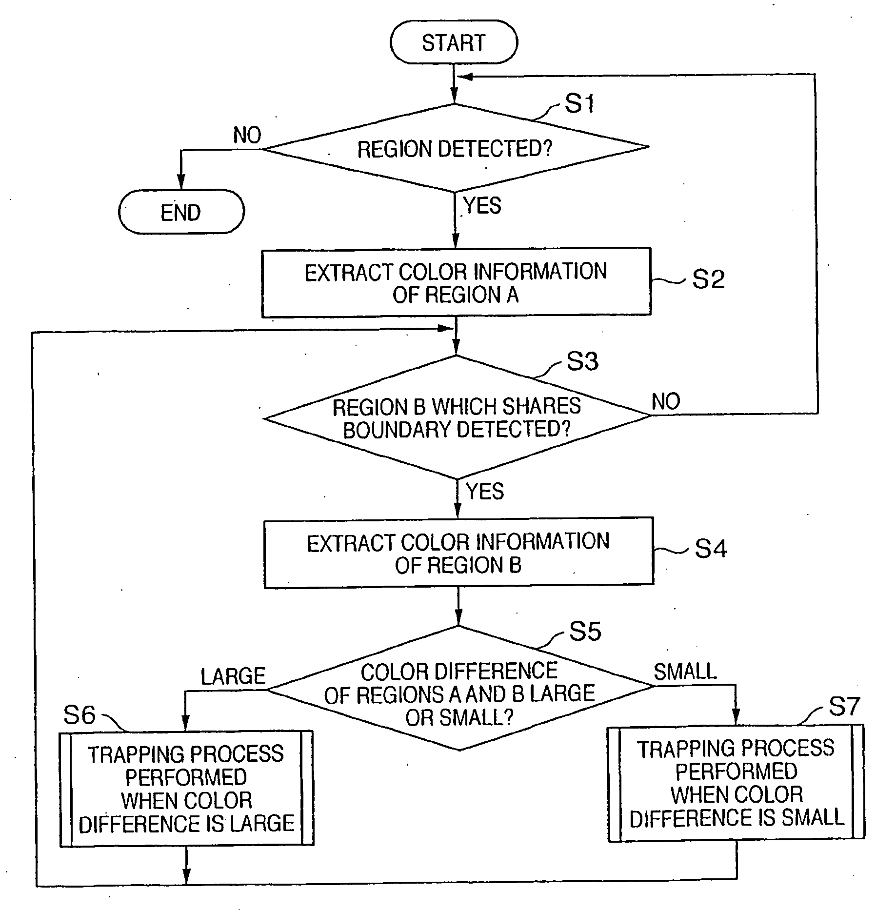
[0083]In the trapping processes performed when the color difference is large and small shown in FIGS. 14 and 19, an example of processing the color information of the regions A and B in order to set the color of the trap region after color separation processing has been described. However, a blank portion can be prevented by generating a trap region so as to have the color information indicating that the trap region uses the same color as the expanded region and the density of the color becomes equal to or more than the predetermined value.

[0084]FIG. 20 is a flowchart showing an example of the trapping process (S6) performed when the color difference is large, in which the same processes as in FIG. 14 are performed except step S37. More specifically, when a blank portion may appear, a trap region using a color which neither region A nor B uses is generated by center trapping (S37). For example, in the case of M+LM, center trapping using a fluorescent pink, ...


PUM


Abstract

In forming an image including a spot color, when an image for which a trapping process is performed does not include information of a spot color, the trapping process sometimes functions ineffectively. To solve this problem, image data having information of colors less in number than the colors included in the image is input and two adjacent regions are detected from the input image data. When the color information is color-separated into the colors, it is determined if the two regions share the color, and trapping for an adjacent portion of the two regions is controlled.

Description

TECHNICAL FIELD[0001]The present invention relates to image processing for generating image data for forming a visible image by overlaying a plurality of colors.BACKGROUND ART[0002]An image forming apparatus such as an electrophotographic laser beam printer, copying machine, multi-functional peripheral equipment, and the like uses a powder color material or liquid color material (to be referred to as toner or ink) to form a visible image on a printing medium.[0003]For example, an electrophotographic image forming apparatus performs laser scanning on the surface of a charged image carrier and exposes it in accordance with image data, thereby forming an electrostatic latent image. The apparatus then supplies color materials to the image carrier to develop the electrostatic latent image, and transfers and fixes the developed image on a printing medium to form a visible image on it.[0004]A printing machine other than the electrophotographic one also forms a desired visible image by over...

Claims


Application Information

Patent Timeline
Patent Type & Authority Applications(United States)
IPC IPC(8): H04N1/46H04N1/60
CPCH04N1/58
Inventor TAKEISHI, HIROKI
Owner CANON KK
Why Eureka
Try Eureka