Monitoring system for internal combustion engine

Active Publication Date: 2008-11-20
DENSO CORP
View PDF6 Cites 4 Cited by
  • Summary
  • Abstract
  • Description
  • Claims
  • Application Information

AI Technical Summary

Benefits of technology

[0009]Since both actual fuel injection quantity and the actual fuel injection timing can be monitored, an existence of the fuel injection malfunction can be accurately detected. Even if fuel injection quantity increases, when the actual torque does not increase due to the fuel injection timing, it can prevent performing the erroneous determination that the fuel injection malfunction exists, and can prevent performing the fail-safe processing erroneously.

Problems solved by technology

As the result, it may be determined that the torque is excessively increased and the fuel cut may be performed.
In such a case, even if the combustion mode is the stratified combustion which is suitable for the fuel-quantity-base actual torque, the computation accuracy of the fuel-quantity-base actual torque is deteriorated so that it cannot be accurately determined whether a torque malfunction exists.

Method used


Image

  • Monitoring system for internal combustion engine
  • Monitoring system for internal combustion engine
  • Monitoring system for internal combustion engine

Examples


Embodiment Construction

[0016]An embodiment of the present invention will be described hereinafter.

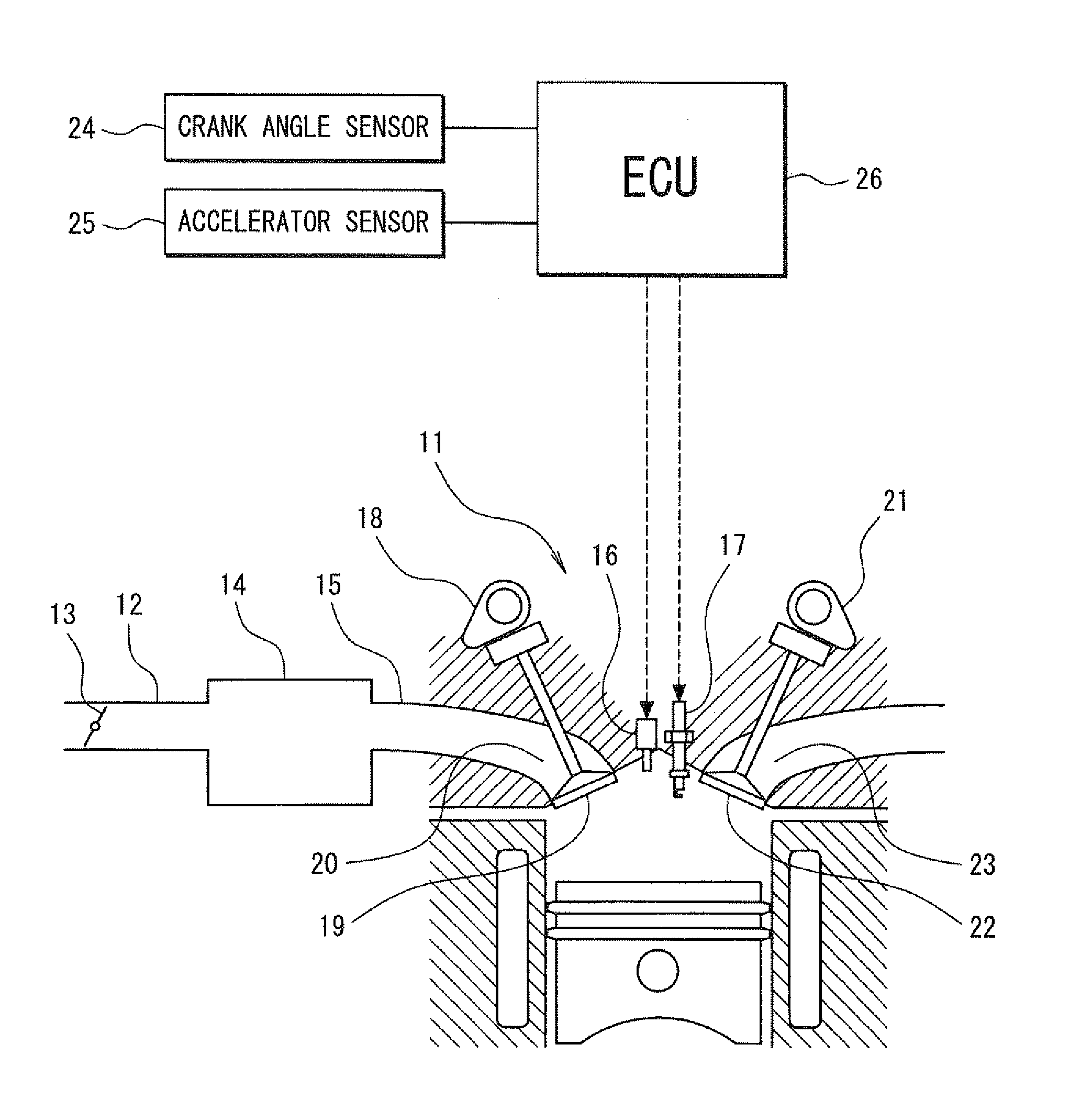
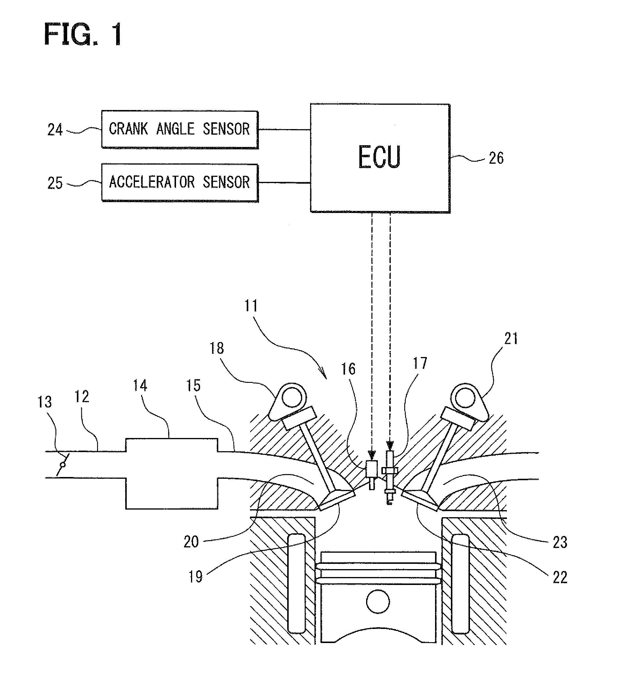
[0017]Referring to FIG. 1, an engine control system is explained. An intake pipe 12 of a direct injection engine 11 is provided with a throttle valve 13 of which position is controlled by a motor (not shown). A surge tank 14 is provided down steam of the throttle valve 13. An intake air manifold 15 is connected to the surge tank 14 to introduce air into the engine 11.

[0018]A fuel injector 16 is provided on an upper portion of each cylinder of the engine 11 to inject fuel directly into the cylinder. A spark plug 17 is mounted on a cylinder head of the engine 11 corresponding to each cylinder to ignite air-fuel mixture in each cylinder. An intake valve 19 is driven by an intake cam 18 to open and close an intake port 20. An exhaust valve 22 is driven by an exhaust cam 21 to open and close an exhaust port 23.

[0019]A crank angle sensor 24 is installed on a cylinder block to output crank angle pulses when a cranks...


PUM


Abstract

An injection pulse output portion outputs an injection pulse to the fuel injector based on a target fuel injection timing and a target fuel injection quantity. A fuel injection monitor portion computes an actual fuel injection timing and an actual fuel injection quantity and determines that there is an malfunction in fuel injection when a difference between the actual fuel injection timing and a target fuel injection timing is larger than a specified value and when a difference between the actual fuel injection quantity and a target fuel injection quantity is larger than a specified value. According to a combustion mode, a torque monitor portion defines one of an air-quantity-base actual torque and a fuel-quantity-base actual torque as a malfunction determination actual torque to determine whether a torque malfunction exists. When the fuel injection malfunction exists, the air quantity base torque is defined as the malfunction determination actual torque.

Description

CROSS-REFERENCE TO RELATED APPLICATION[0001]This application is based on Japanese Patent Application No. 2007-129805 filed on May 15, 2007, the disclosure of which is incorporated herein by referenceFIELD OF THE INVENTION[0002]The present invention relates to a monitoring system for an internal combustion engine which determines whether the engine has a malfunction.BACKGROUND OF THE INVENTION[0003]JP-P2005-522617A (U.S. Pat. No. 7,194,997B2) shows monitoring method for an internal combustion engine in which a current torque is computed based on an actual fuel injection quantity and / or a target fuel injection quantity. When the current torque is larger than a permissible torque, a fuel cut is performed.[0004]In a certain driving condition of the engine, even if fuel injection quantity increases, the actual torque may not increase unless a fuel injection timing is changed. In the above method, since the current torque is computed based on a fuel injection quantity without considering ...

Claims


Application Information

Patent Timeline
IPC IPC(8): F02D41/30
CPCF02D41/221F02D41/3029F02D41/40F02D2200/0602F02D2200/0606F02D2200/1004Y02T10/44Y02T10/40
Inventor MURAKAMI, YOSHIFUMI
Owner DENSO CORP
Why Eureka
Try Eureka