
Electrode for secondary battery having fine holes

Active Publication Date: 2019-07-25
LG ENERGY SOLUTION LTD
View PDF5 Cites 1 Cited by
  • Summary
  • Abstract
  • Description
  • Claims
  • Application Information

AI Technical Summary

Benefits of technology

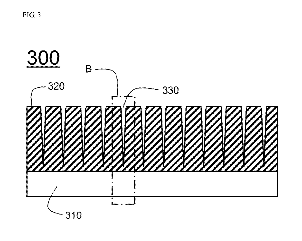
The present disclosure describes an electrode for a secondary battery that includes a layer with multiple small holes that decrease in size towards the current collector. This design allows the electrolyte solution to easily diffuse through the holes, preventing the formation of plating and maintaining good electrical performance. Additionally, the smooth movement of lithium ions during charging and discharging improves rapid charging performance. Compared to conventional methods, this design utilizes molds or rollers with protrusions to create the holes, eliminating potential capacity decrease and reducing defect rates.

Problems solved by technology

Depletion of fossil fuel has brought about a great increase in the price of energy sources and increased interest in environmental pollution.
However, in a case of an electrode having a very high loading amount of the electrode mixture layer, a thickness of the electrode mixture layer is excessively large, and thus diffusion of an electrolytic solution does not easily occur in a depth direction of the electrode mixture layer.
In particular, as a demand for mobile devices has increased, studies on batteries capable of being rapid charged have been conducted, however, due to the above-mentioned problems, in a case of an electrode having a high loading amount of the electrode mixture layer to maximize the capacity of the electrode, rapid charging may become more difficult.
That is, when increasing the loading amount of the electrode mixture layer formed on the current collector to maximize the capacity of the electrode, diffusion of the electrolytic solution does not easily occur in the depth direction of the electrode mixture layer.
And this causes the Li-plating phenomenon, or in the case of a secondary battery including an electrode having a high loading amount of the electrode mixture layer, rapid charging may become more difficult.

Method used


Image

  • Electrode for secondary battery having fine holes
  • Electrode for secondary battery having fine holes
  • Electrode for secondary battery having fine holes

Examples


example 1

[0078]Artificial graphite, carbon black, CMC, and SBR were mixed with distilled water at a weight ratio of 95.8:1:1.2:2 to prepare a negative electrode slurry. The negative electrode slurry was coated on a copper foil to form a thin electrode plate, dried at 135° C. for 3 hours or more, and rolled to prepare a negative electrode mixture. A loading amount of the negative electrode mixture was 4.5 mAh / cm2, and a volume of pores having a pore diameter of about 0.5 to 3 μm was 30%. As shown in FIG. 5, a fine hole forming mold in which horn-shaped protrusions were formed was pressed against a surface of a negative electrode mixture layer to form a plurality of fine holes recessed in the horn-shape in the negative electrode mixture layer. In particular, a diameter of each of the fine holes was 200 micrometers at a surface part thereof and 35 micrometers at an inner end part thereof.

[0079]For a positive electrode, Li(Ni1 / 3Co1 / 3Mn1 / 3)O2 was used as a positive electrode active material, whic...

example 2

[0082]A battery was manufactured in the same manner as in Example 1 except that the loading amount of the negative electrode was changed to 3.7 mAh / cm2 and the porosity was changed to 34%.

example 3

[0083]A battery was manufactured in the same manner as in Example 1 except that the loading amount of the negative electrode was changed to 5.3 mAh / cm2 and the porosity was changed to 27%.


PUM


Abstract

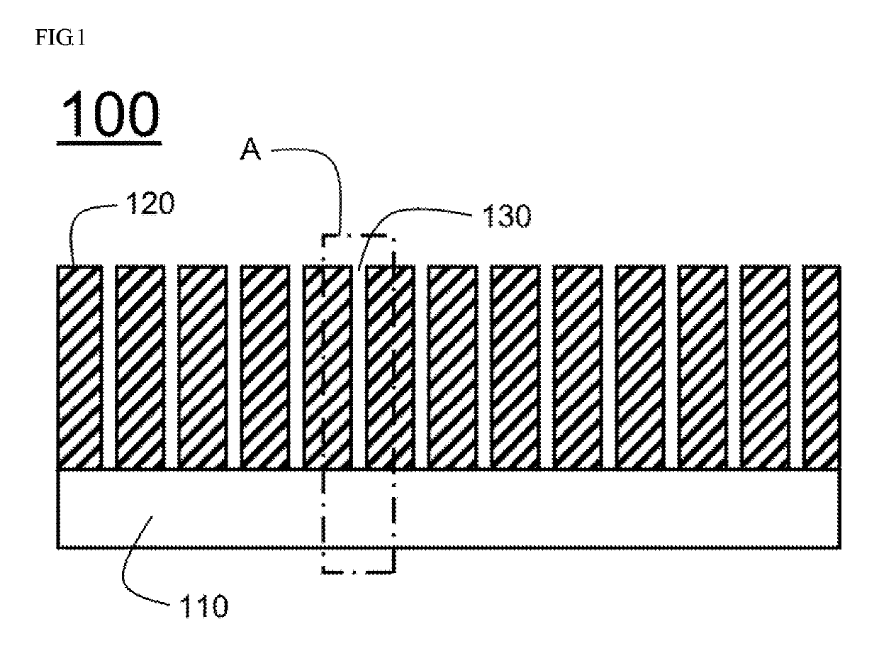
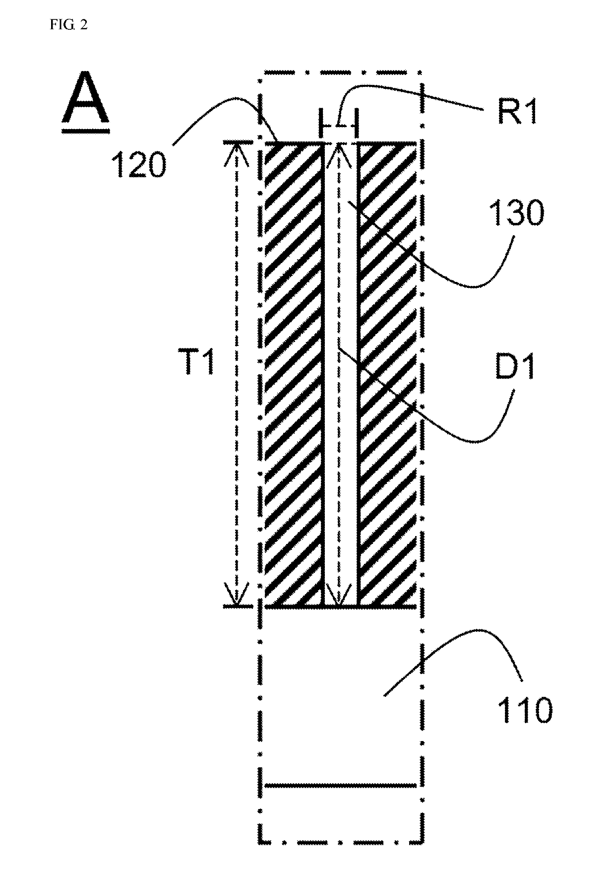
Disclosed herein is an electrode for a secondary battery including an electrode mixture layer including an electrode active material on one surface or both surfaces of a current collector, wherein the electrode mixture layer includes a plurality of fine holes recessed toward the current collector from a vertical cross-sectional surface, and each of the fine holes is a horn-shaped hole whose diameter is gradually decreased from the vertical cross-sectional surface toward the current collector in the electrode mixture layer.

Description

TECHNICAL FIELD[0001]The present disclosure relates to an electrode for a secondary battery having fine holes.BACKGROUND ART[0002]Depletion of fossil fuel has brought about a great increase in the price of energy sources and increased interest in environmental pollution. Eco-friendly alternative energy sources are a necessity for the next generation. In this regard, a great deal of research into power production methods such as methods of producing nuclear energy, sunlight power, wind power, and tidal power is underway, and a power storage device for efficiently utilizing the produced energy is also attracting much attention.[0003]Particularly, as mobile devices have been increasingly developed and the demand for such mobile devices has increased, the demand for secondary batteries has also sharply increased as an energy source for the mobile devices. Accordingly, much research into batteries satisfying various needs has been carried out.[0004]In terms of the shape of batteries, the...

Claims


Application Information

Patent Timeline
IPC IPC(8): H01M4/66H01M4/136H01M4/139H01M4/36H01M10/0525H01M4/04
CPCH01M4/665H01M4/136H01M4/139H01M4/364H01M10/0525H01M4/0404H01M2004/021H01M2004/028H01M2004/027H01M4/13H01M4/0435H01M4/1393Y02E60/10Y02P70/50
Inventor LEE, SOL NIPLEE, HYEOK MOOOH, SONG TAEK
Owner LG ENERGY SOLUTION LTD
Learn More