

Improved flute headjoint
- Summary
- Abstract
- Description
- Claims
- Application Information
AI Technical Summary
Benefits of technology
Problems solved by technology
Method used
Image


Examples
Embodiment Construction
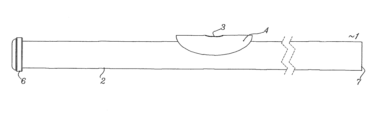
[0047]In FIG. 1 a view of the flute headjoint 1 according to the invention is shown, which consists of a pipe section 2 configured similarly to, but longer than conventional headjoints, with an element 4 bounding an embouchure hole 3 being disposed on the pipe section 2. A so-called sonic chamber 5 is disposed in the part of the pipe section 2 of the flute headjoint 1 situated under the embouchure hole 3. The sonic chamber 5 is terminated at the side facing the crown 6 by a so-called tuning plug 8. The sonic chamber 5 is essentially a region with an approximate size of 4 cm, with the air blown in through the embouchure hole 3 flowing in the direction of the free end 7 of the pipe section 2 through the middle of this region. The body of the flute with the keywork adapted for playing the instrument is attached to the free end of the pipe section 2 of the flute headjoint 1. In the region of the flute headjoint 1 near the crown 6 there is situated a tuning plug 8. The blown-in air colli...
PUM
 Abstract
Description
Claims
Application Information