
Dynamic variable orifice for compressor pulsation control

a compressor and variable orifice technology, applied in machines/engines, liquid fuel engines, positive displacement liquid engines, etc., can solve the problems of affecting the thermodynamic performance of the compressor, affecting and severely compromising the reliability, performance and structural integrity of the reciprocating compressor and its connected system. to achieve the effect of increasing or reducing the effective orifice size or restriction

Active Publication Date: 2018-11-01
ACI SERVICES
View PDF0 Cites 0 Cited by
  • Summary
  • Abstract
  • Description
  • Claims
  • Application Information

AI Technical Summary

Benefits of technology

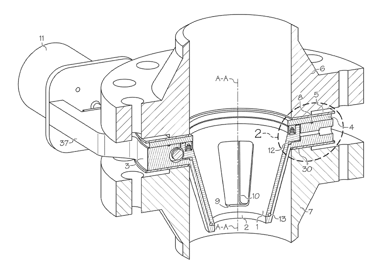
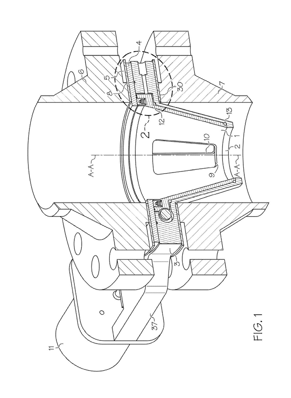
[0016]Accordingly, the present invention relates to a pulsation dampening apparatus which provides the ability to adjust its effective orifice size or restriction. The inventive pulsation dampening apparatus can also be referred to herein as a “dynamic variable orifice” (DVO). The invention provides a practical means of changing the effective orifice sizes to optimal values in response to changing compressor operating conditions. The DVO can be adjusted while the compressor is operating and pressurized, and allows a user to increase or decrease the effective orifice size or restriction. The orifice size of the DVO can be adjusted manually with a wrench or hand crank, or automatically with the assistance of an electrical, pneumatic or hydraulically powered actuator or motor. The power-assisted adjustment may be controlled by a human operator, or by an automatic control system programmed to automatically adjust the orifice size as operating conditions change.
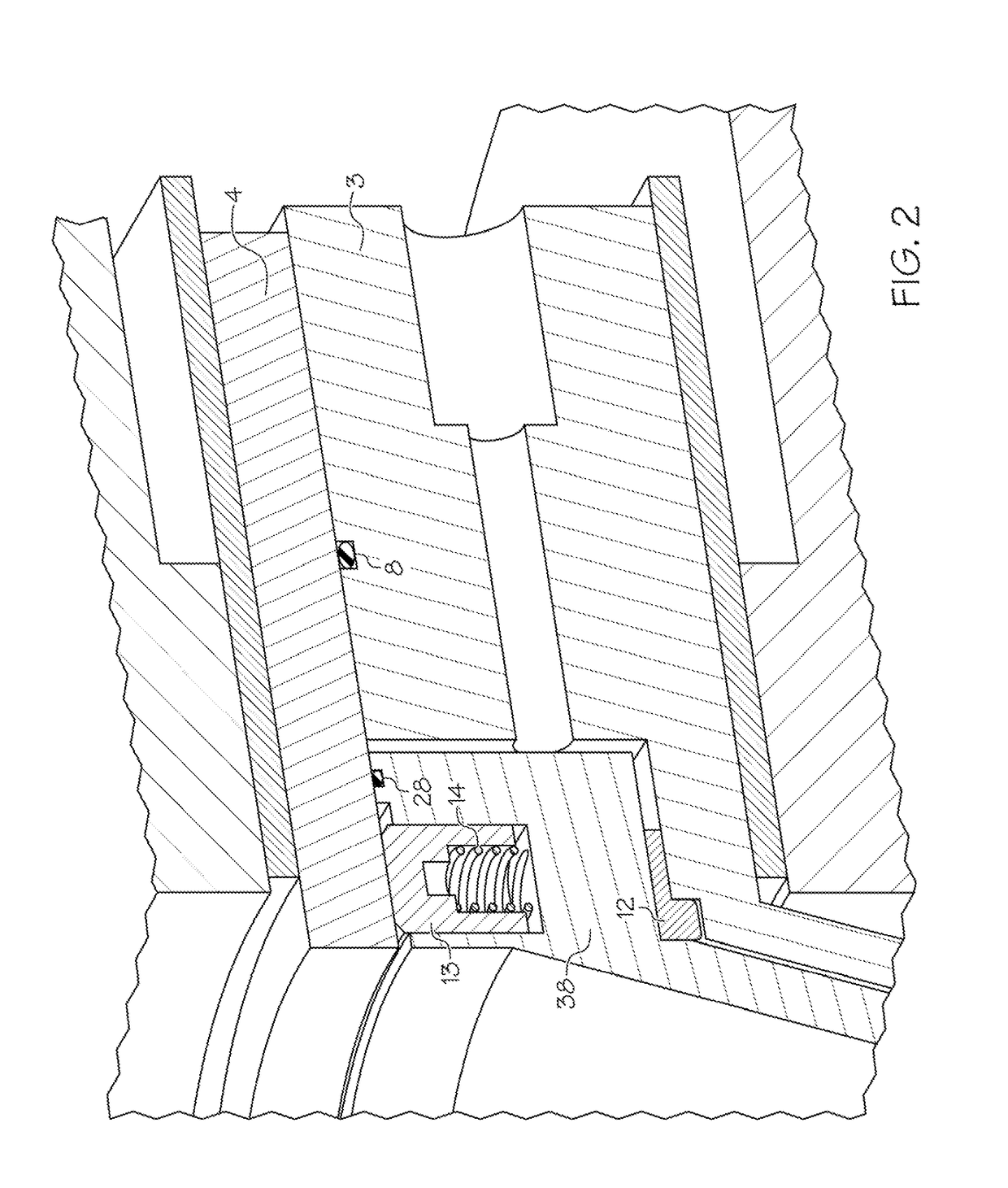
[0018]A second aspect of the invention provides a pulsation dampening apparatus for providing a variable effective orifice size for a reciprocating compressor, the pulsation dampening apparatus comprising: (a) a fixed inner conical cage including a plurality of inner conical cage ports; (b) a rotatable outer conical cage including a plurality of outer conical cage ports; (c) a central cylindrical port created by alignment of the inner conical cage and the outer conical cage about a central axis, wherein the inner conical cage and the outer conical cage have mating contours allowing the rotatable outer conical cage to slide over the fixed inner conical cage as it rotates about the central axis, rotation of the outer conical cage causing the plurality of inner conical cage ports and the plurality of outer conical cage ports to be selectively aligned, the relative alignment of the plurality of inner conical cage ports with the plurality of outer conical cage ports determining the effective orifice size of the apparatus; and (d) a bevel gear drive including a shaft having rotatable gear teeth, the outer conical cage further including a flange including fixed gear teeth which engage the rotatable gear teeth, wherein rotation of the rotatable gear teeth causes the outer conical cage to be rotated, rotation of the outer conical cage causing a change in the orientation of the plurality of outer conical cage ports with respect to the plurality of inner conical cage ports, thereby allowing a adjustment of the apparatus to any desired effective orifice size.

Problems solved by technology

The pulsations may excite system mechanical natural frequencies, cause high vibration, overstress system elements and piping, interfere with meter measurements, and affect compressor thermodynamic performance.
These effects can severely compromise the reliability, performance and structural integrity of the reciprocating compressor and its connected system, as well as flow meters and other compressors connected to the system.
This added resistance causes system pressure losses and energy losses both upstream and downstream of the compressor cylinders.
The pressure and energy losses typically increase as the frequency of the pulsation increases, and these losses add to the work that must be done by the compressor to move fluid from the suction line to the discharge line.
However, smaller and larger diameter ratios are sometimes used.
Fixed orifice plates are effective in reducing pulsations over a narrow compressor operating range, however they cause an associated pressure drop that adds to the work and power consumption required by the compressor.
For example, a very restrictive (low diameter ratio) fixed orifice plate may be required to adequately dampen pulsations at certain operating conditions.
In addition, a fixed orifice plate that controls pulsations with a tolerable pressure drop and power penalty at some conditions, may cause excessive damping, pressure drop and power penalty at other conditions.
There are therefore multiple challenges when trying to achieve pulsation control with pulsation bottles and fixed orifice plates.
Additionally, the pulsation dampening will be generally good at normal and high flow conditions, but may be marginal to poor at certain frequencies when operating at the minimum flow conditions.”
Although a fixed orifice plate having a specific diameter may be necessary and effective for pulsation control at one set or range of operating conditions, it may be unnecessary, ineffective, and / or the cause of unacceptably high pressure drop and associated power consumption at other ranges of operating conditions.
Accordingly, the downtime, labor and lost production required for changing fixed orifice plates make this alternative impractical.
As a result, compressor systems tend to run with higher pressure and power losses or with higher pulsation induced vibration, and associated risk, than would be optimal if the orifice size could be changed when dictated by operating conditions.
In many cases the range of operating conditions has to be reduced or limited to restrict the operation of the compressor system.

Method used


Image

  • Dynamic variable orifice for compressor pulsation control
  • Dynamic variable orifice for compressor pulsation control
  • Dynamic variable orifice for compressor pulsation control

Examples


case 1

[0068 is a 1200 rpm operating point with all four cylinders in double acting mode, but with volumetric clearance added to each head or lower cylinder end to reduce the capacity to a rate of 86.5 million standard cubic feet per day (MMSCFD).

case 3

[0069 is a 1084 rpm operating point with three of the four cylinders in single acting mode (i.e., suction valves removed or disabled to allow gas to bypass them, leaving only the crank or frame end of the cylinder able to compress gas) and with the fourth cylinder in double acting mode, but with volumetric clearance added to the head or lower end of that cylinder to reduce capacity to a rate of 58.0 MMSCFD.

case 8

[0070 is a 1200 rpm operating point with all four cylinders in double acting mode with no volumetric clearance added to the head or lower cylinder end for a capacity of 149.9 MMSCFD. This provides maximum capacity from the compressor.

[0071]As is customary with the current state of the art, a common set of fixed pulsation control orifices was selected for all operating conditions. The common set consists of 5.50 in. diameter orifices for [SRO-1], 3.75 in, diameter orifices for [SRO-2], 350 in, diameter orifices for [DRO-1], and 4.25 in. diameter orifices for [DRO-2].

[0072]The data in FIGS. 11A and 11B shows that a common set of fixed pulsation control orifices is far from optimal. The set was selected to provide best overall performance at Operating Case 1, which is the highest power condition of the cases shown. With the common set of fixed orifices, the suction (from the suction header to the compressor suction flange) and discharge (from the compressor discharge flange to the disc...


PUM


Abstract

A pulsation dampening apparatus for providing a selectively variable orifice size fir a reciprocating compressor system includes a rotatable conical cage and a fixed conical cage, the conical cages being aligned along a central axis to firm a central cylindrical port. The conical cages each include at least one window or port and have mating contours allowing the conical cages to rotatably slide over one another, allowing their respective ports to be selectively aligned in any configuration to create any desired effective orifice size. In one embodiment, each of the conical cages include a plurality of ports which can be selectively aligned, the relative alignment of the ports determining the effective orifice size of the pulsation dampening apparatus.

Description

CROSS-REFERENCE TO RELATED APPLICATIONS[0001]This application is a continuation-in-part of U.S. application Ser. No. 14 / 602,515 filed Jan. 22, 2015, which claims the benefit of U.S. Provisional Application No. 61 / 930,275, filed Jan. 22, 2014 and U.S. Provisional Application No. 62 / 033,835, filed Aug. 6, 2014, the disclosures of which are incorporated herein by reference in their entirety.FIELD OF THE INVENTION[0002]The present invention relates in general to the control of the flow of pressurized fluids through industrial and commercial piping systems, and in particular to a dynamic variable device for dampening pressure and flow pulsations passing through these systems, especially to systems that include one or more reciprocating (piston-type) compressor cylinders with variable operating conditions.BACKGROUND OF THE INVENTION[0003]Reciprocating compressors typically include one or more pistons that “reciprocate” within closed cylinders. They are commonly used for a wide range of ap...

Claims


Application Information

Patent Timeline
Patent Type & Authority Applications(United States)
IPC IPC(8): F04B11/00F04B19/22F04B39/00F04B49/22F15D1/00F04B53/00F04C29/00
CPCF04B11/0091F04B19/22F04B39/0072F04B49/22F04C2270/86F04B53/001F04C29/0035F04C2240/81F15D1/0005F04B39/0055F04B41/06F04B49/225
Inventor ADAIR, JARED W.
Owner ACI SERVICES
Learn More