
A sensor comprising two parallel acoustical filter elements, an assembly comprising a sensor and the filter, a hearable and a method

Inactive Publication Date: 2018-11-01
SONION NEDERLAND
View PDF4 Cites 2 Cited by
  • Summary
  • Abstract
  • Description
  • Claims
  • Application Information

AI Technical Summary

Benefits of technology

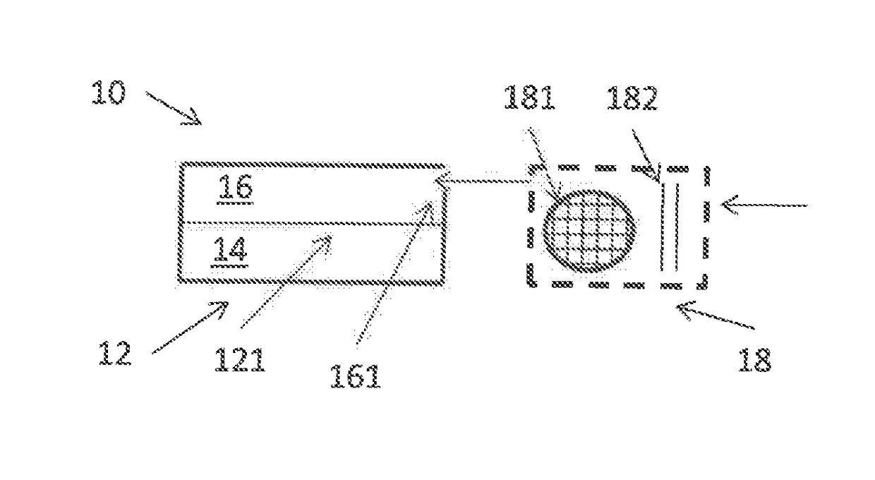
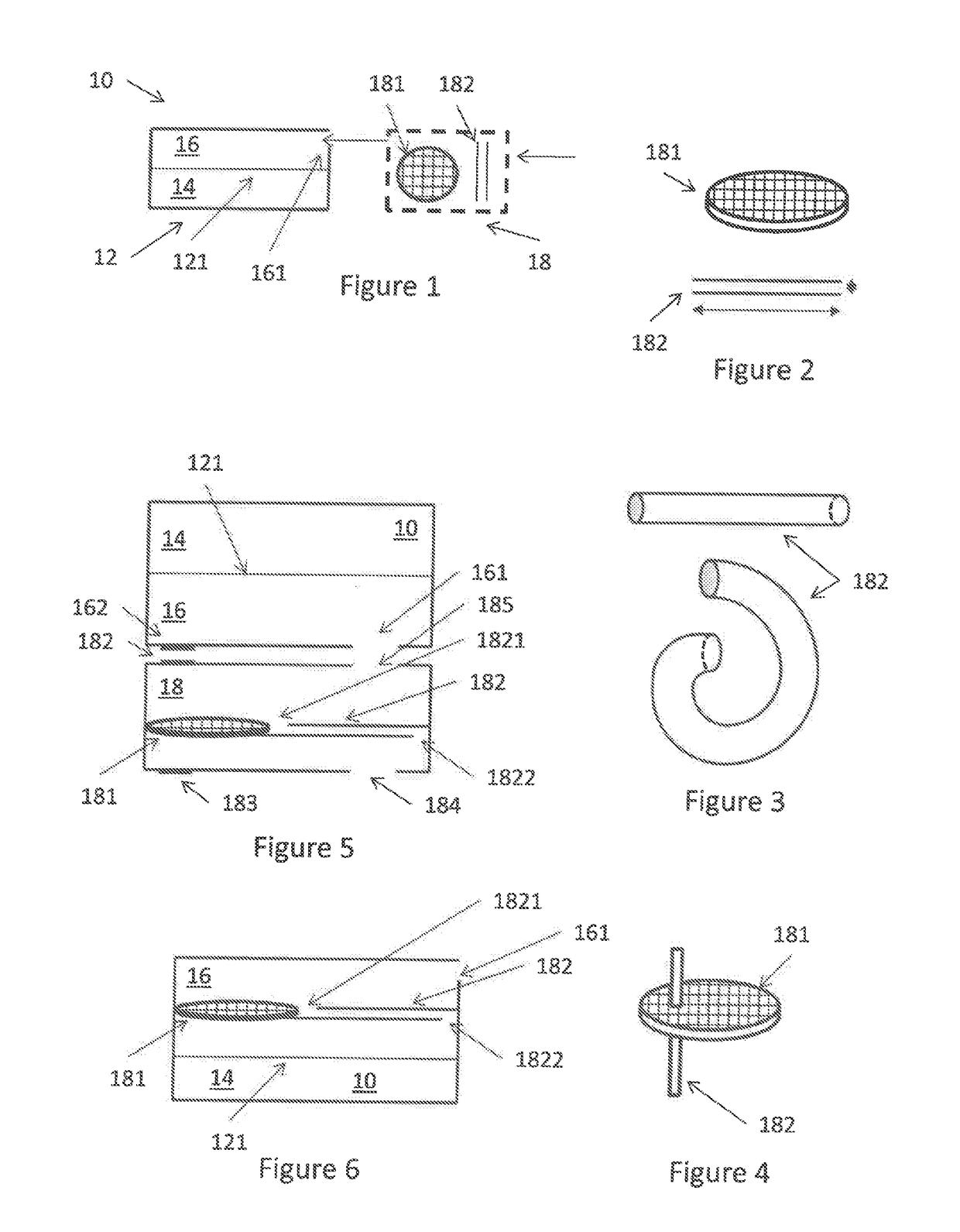
The patent describes a way to filter out background noise while still getting good quality acoustic information. This can be achieved by adding a small noise-based filter that can be placed where the original sensor was designed to be placed, without needing to redesign the whole system. This results in less noise and better quality sound data.

Problems solved by technology

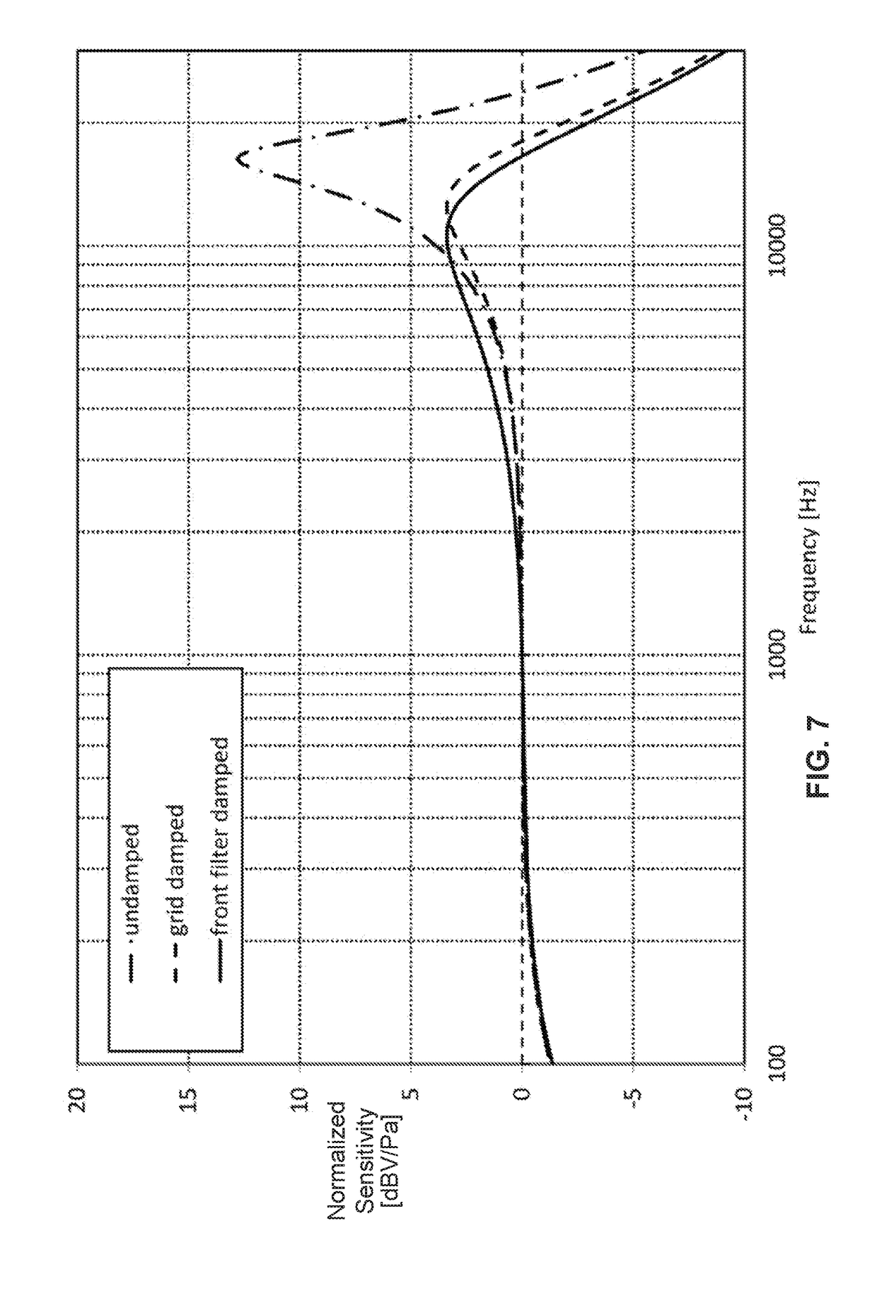
Acoustical peak damping is a known microphone designer issue.

Method used


Image

  • A sensor comprising two parallel acoustical filter elements, an assembly comprising a sensor and the filter, a hearable and a method
  • A sensor comprising two parallel acoustical filter elements, an assembly comprising a sensor and the filter, a hearable and a method
  • A sensor comprising two parallel acoustical filter elements, an assembly comprising a sensor and the filter, a hearable and a method

Examples


embodiment 1

[0278]2. A sensor , wherein the first filter element comprises one or more first channels each with a first length.

embodiment 2

[0279]3. A sensor , wherein a combined cross section of the first channel(s) divided by the first length preferably is above a predetermined threshold.

[0280]4. A sensor according to any of the above embodiments, wherein the first filter element comprises a grid comprising a number of openings forming the first channels, the grid having a thickness defining the first length.

[0281]5. A sensor according to any of the preceding embodiments, wherein the first filter element comprises one or more of a grid, a woven, a non-woven and a porous material.

[0282]6. A sensor according to claim 5, wherein the first filter element has a thickness of 0.01-1 mm, such as 0.02-0.5 mm, such as 0.03-0.3 mm, such as below 0.015 mm.

[0283]6.1. A sensor according to claim 5 or 6, wherein the first opening of the first filter element has a number of sound openings, where a ratio between open and closed surface is <80%, such as <60%, <40%, <30%, <20% or <10%.

[0284]6.2. A sensor according to any of claims 5, 6 ...

embodiment 12

[0292]13. A sensor , wherein the channel is elongate, straight or bent / curled.

[0293]14. A sensor according to any of the preceding embodiments, further comprising a sensor housing, in which the movable element is positioned, and a filter housing positioned outside of the sensor housing, wherein:[0294]the sensor housing has a sound input,[0295]the filter housing has a sound input and a sound output, the sound output positioned so that sound may be output from the sound output and enter the sensor housing sound input,[0296]the first and second filter elements are positioned in the filter housing, and[0297]the filter housing has elements guiding sound entering the sound input through the first and second filter elements and toward the sound output.


PUM


Abstract

A sensor having a movable element, such as a microphone with a diaphragm, where received sound is filtered by two parallel acoustical filters before being sensed by the sensor, where one acoustical filter has a larger acoustical resistance and a lower acoustical mass than the other.

Description

CROSS-REFERENCE TO RELATED APPLICATIONS[0001]This application claims the benefit of European Patent Application Serial No. 17159020.1, filed Mar. 2, 2017, which is incorporated herein by reference in its entirety.FIELD OF THE INVENTION[0002]The present invention relates to a sensor with a parallel acoustical filter which reduces a sensitivity peak without adding as much noise as hitherto.BACKGROUND OF THE INVENTION[0003]Acoustical filters and hearables may be seen in US20120177229, U.S. Pat. No. 9,380,377, U.S. Pat. No. 9,351,084, U.S. Pat. No. 8,879,767, EP 2 608 570, U.S. Pat. No. 9,185,498, EP2826258, WO2011001405, WO2016 / 102923, U.S. Pat. No. 2,865,464, US2004 / 084244, US2005 / 069164, US2008 / 157301, WO97 / 47117, DE1437371, and U.S. Pat. No. 8,184,845.[0004]Acoustical peak damping is a known microphone designer issue. In order to avoid overload problems at the input of the hearing aids, HA manufacturers usually require a microphone response to be as flat as possible (compared to the...

Claims


Application Information

Patent Timeline
IPC IPC(8): H04R25/00
CPCH04R25/453H04R25/505H04R25/65H04R1/021H04R1/2876H04R19/005
Inventor MIMOUN, BENJAMIN ABRAHAM ZEEVDE NOOIJ, MICHEL
Owner SONION NEDERLAND
Learn More