Method and Apparatus for Producing High Extinction Ratio Data Modulation Formats

Inactive Publication Date: 2007-12-06
XTERA COMM
View PDF9 Cites 2 Cited by
  • Summary
  • Abstract
  • Description
  • Claims
  • Application Information

AI Technical Summary

Benefits of technology

[0014] The optical modulation method of the present invention gives rise to a data format with a high extinction ratio compared with conventional optical data formats. The combination of the electric field transfer function of each of the modulators and the power transfer function of the modulator superstructure means that the zero power level is compressed, mitigating the effect of noise in the electrical data signals. A further advantage of the present invention is that it may be used to obtain a wide variety of optical data modulation formats.
[0015] Preferably, the first and second modulators are electro-optic modulators. More preferably, they are Mach-Zehnder modulators.
[0016] Preferably, the optical modulators are driven with RZ data. Electrical RZ drivers typically give rise to less noise than electrical NRZ drivers. Nevertheless, the optical modulators may also be driven with NRZ data.
[0017] Preferably, a delay is applied to the data driving one of the first and second optical modulators. More preferably, the magnitude of this delay is any one of: 0 bits; 1 bit; or, any value between 0 bits and 1 bit. The ability to apply such a delay allows a the selection of a variety different data modulation formats.
[0018] In some embodiments of the present invention, the logical polarity of the data driving one of the first and second modulators is inverted. This feature allows the selection of further data modulation formats.
[0019] According to a second aspect of the present invention, an optical transmitter for transmitting optically encoded data comprising a coherent light source and a modulator structure, the modulator structure including:

Problems solved by technology

Most long distance networks are impaired by the loss of the optical transmission fibre.
These amplifiers provide signal gain but also produce optical noise known as Amplified Spontaneous Emission (ASE).
The optical noise mixes with the optical signal at the receiver photodiode, producing electrical beat noise.
However light in the ‘0’s is unavoidable due to the noisy electrical drive signal being converted into optical noise at the modulation stage.

Method used


Image

  • Method and Apparatus for Producing High Extinction Ratio Data Modulation Formats
  • Method and Apparatus for Producing High Extinction Ratio Data Modulation Formats
  • Method and Apparatus for Producing High Extinction Ratio Data Modulation Formats

Examples


Embodiment Construction

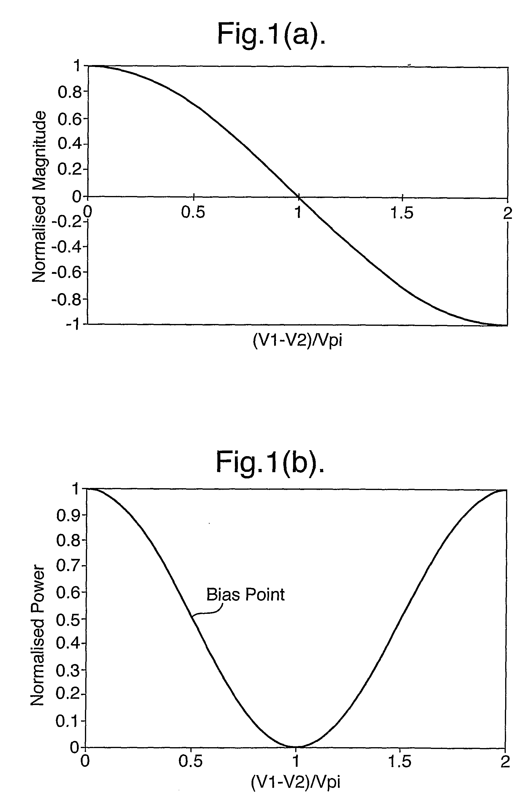
[0037]FIG. 1a illustrates the electrical field transfer function of a typical x-cut zero-chirp Lithium Niobate Mach-Zehnder (MZ) modulator. The applied voltage is shown on the x-axis as a normalised difference between the voltage applied to the two arms of the modulator, and the resultant electrical field output is shown as a normalised value on the y-axis. The x-axis is divided into units of V1-V2 / Vpi, where V1 is the voltage applied to a first arm of the modulator, V2 is the voltage applied to the other arm of the modulator and Vpi is the voltage difference between V1 and V2 required to give rise to a phase shift of 180° i.e. destructive interference at the output and hence zero electric field. The units of the y-axis are normalised by the maximum electric field at the output.

[0038]FIG. 1b shows the power transfer function corresponding to the square of the electrical field transfer function of FIG. 1a. The typical constant bias point about which the modulator is driven is indica...


PUM


Abstract

The present invention provides both a method and an apparatus for optically encoding data. Light from a coherent source is split into two separate light signals, and each of these light signals is modulated with the data such that the data levels output correspond to the points of maximum optical power. One of the modulated light signals is phase biased to be in phase or in anti-phase with the other modulated light signal and the two light signals are then combined to form a combined optical output. The present invention enables the resulting combined optical output to be a data format with a high extinction ratio compared with conventional optical data formats. It can be used to produce a wide variety of optical data modulation formats.

Description

FIELD OF THE INVENTION [0001] The invention relates to optical data formats for optical data transmission, and in particular to data formats with a high extinction ratio. BACKGROUND TO THE INVENTION [0002] Optical data transmission is widely used for long haul, short haul, and metro network based systems. Typically, optical data is provided by electrically modulating light from a coherent light source, using an electro-optic modulator. High performance electro-optic modulators are usually based on a Mach-Zehnder (MZ) interferometer structure. [0003] Most long distance networks are impaired by the loss of the optical transmission fibre. The loss is usually overcome by the use of optical amplifiers. These amplifiers provide signal gain but also produce optical noise known as Amplified Spontaneous Emission (ASE). The optical noise mixes with the optical signal at the receiver photodiode, producing electrical beat noise. This noise usually dominates the receiver's Optical Signal to Nois...

Claims


Application Information

Patent Timeline
IPC IPC(8): H04B10/18H04B10/50H04B10/516
CPCH04B10/505H04B10/5053H04B10/5167H04B10/5165H04B10/5055
Inventor OBERLAND, RICHARD
Owner XTERA COMM
Why Eureka
Try Eureka