
Wave seal for filter element

a filter element and seal element technology, applied in the direction of separation process, filtration separation, dispersed particle separation, etc., can solve the problems of high cost in the manufacturing process of co-injection molding cover and seal element, and the high cost of various filtration products, so as to improve the sealing and sealing. , the effect of improving the sealing and improving the sealing

Active Publication Date: 2018-11-08
PARKER INTANGIBLES LLC
View PDF8 Cites 21 Cited by
  • Summary
  • Abstract
  • Description
  • Claims
  • Application Information

AI Technical Summary

Benefits of technology

The present invention is a filter element that can better seal and filter air. It can be installed and replaced easily, allowing for increased efficiency and capacity. The manufacturing process is also more cost-effective than traditional methods. Overall, this invention provides a better media air filtration solution.

Problems solved by technology

There also have been issues of high cost in connection with manufacturing various filtration products, and air filtration products in particular.
Although generally effective, such manufacturing process of a co-injection molded cover and seal elements has been somewhat costly.

Method used


Image

  • Wave seal for filter element
  • Wave seal for filter element
  • Wave seal for filter element

Examples


Embodiment Construction

[0022]Embodiments of the present invention will now be described with reference to the drawings, wherein like reference numerals are used to refer to like elements throughout. It will be understood that the figures are not necessarily to scale.

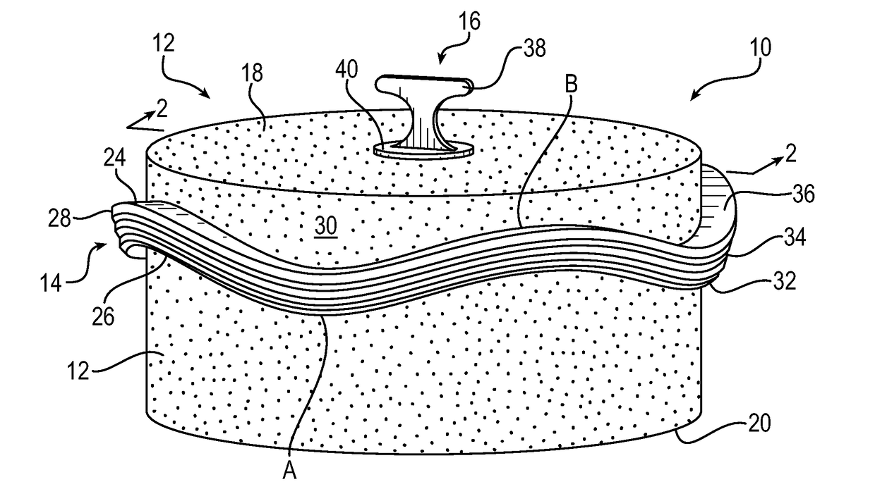
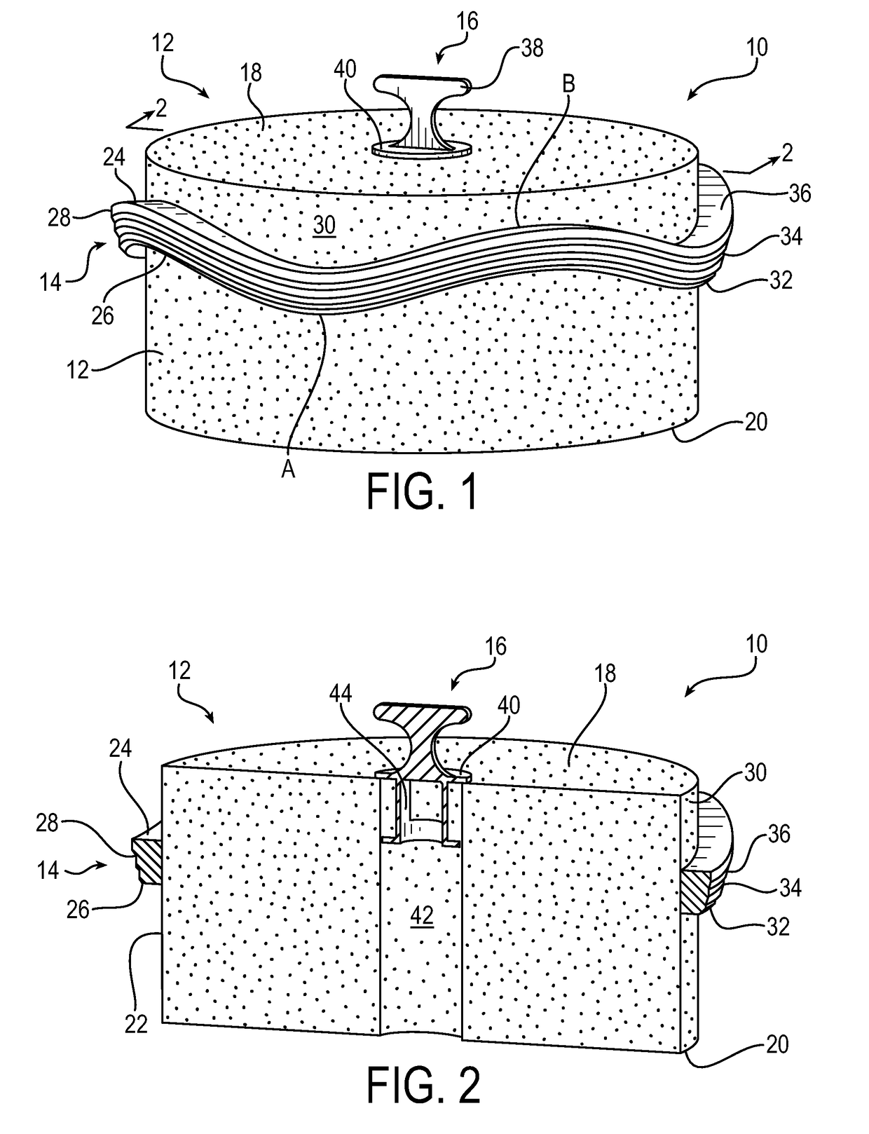
[0023]FIG. 1 is a drawing depicting an isometric view of a first exemplary filter element 10 in accordance with embodiments of the present invention. FIG. 2 is a drawing depicting a side cross-sectional view of the exemplary filter element 10 of FIG. 1. Accordingly, like reference numerals are used in connection with like elements in FIGS. 1 and 2. The filter element 10 is described largely in connection with air filtration products. It will be appreciated, however, that the described principals and configurations may be employed in any suitable filtration application.

[0024]As further described below, in exemplary embodiments, the filter element includes a filter media having a first face and a second face opposite to the first face, and furth...


PUM

PropertyMeasurementUnit
lengthaaaaaaaaaa
diametersaaaaaaaaaa
impermeableaaaaaaaaaa

Abstract

A filter element includes a filter media having opposite first and second faces, and an outer face extending in a longitudinal direction perpendicular from the first face to the second face. An undulating sealing element is directly bonded to the outer face at a location closer to and offset from the first face. The undulations of the sealing element define an offset region of the outer face of the filter media from the first face, the offset region being defined by an amplitude of the undulations. The filter element may be incorporated into a filter assembly including the filter element enclosed by a filter housing. The sealing element may be made of urethane and be compressible within a mating groove in the filter housing.

Description

RELATED APPLICATIONS[0001]This application claims the benefit of U.S. Provisional Application No. 62 / 250,532 filed Nov. 4, 2015, and U.S. Provisional Application No. 62 / 293,545 filed Feb. 10, 2016, which are incorporated herein by reference.FIELD OF INVENTION[0002]The present invention relates generally to fluid filter assemblies, and more particularly to sealing elements for providing a seal of a filter element against a filter housing as may be used in connection with media air filtration products.BACKGROUND OF THE INVENTION[0003]A variety of applications employ fluid filter assemblies. Such applications include, for example, hydraulic systems, fuel delivery systems, coolant systems, and engine lubrication systems. Filter assemblies may be used to filter any type of fluid, such as, for example, air, gasoline, diesel fuel, lubricating oil, water, coolant fluid, and others. Air filtration products in particular are used in a variety of such applications, such as for example in the t...

Claims


Application Information

Patent Timeline
Patent Type & Authority Applications(United States)
IPC IPC(8): B01D46/24B01D46/00B01D35/153
CPCB01D46/2414B01D46/0004B01D46/0005B01D35/153B01D2201/347B01D2201/295B01D2201/296B01D2271/02B01D2265/026
Inventor NICHOLS, JOHNSMITH, JOSHHARBUR, RANDYCOPLEY, DANIEL
Owner PARKER INTANGIBLES LLC
Learn More