Optical pulse detection device, optical pulse detection method, radiation counter device, and biological testing device

a technology of optical pulse detection and biological testing, applied in optical radiation measurement, instruments, television systems, etc., can solve the problems of high cost of photomultiplier tubes, inability to reduce size and weight, and inability to reduce the size and weight of photomultiplier tubes, etc., to achieve accurate and accurate results.

Active Publication Date: 2018-11-15
SONY SEMICON SOLUTIONS CORP
View PDF8 Cites 9 Cited by
  • Summary
  • Abstract
  • Description
  • Claims
  • Application Information

AI Technical Summary

Benefits of technology

The technical effects of this patent are that it can better detect small amounts of light pulses with greater accuracy, and also count the number of rays or particles emitted from a source more accurately. These improvements make it easier to measure and analyze optical signals for various applications such as medical imaging or communication systems.

Problems solved by technology

The technical problem addressed in this patent text is the need for a more affordable and compact radiation counter that can accurately detect and measure the energy of radiation photons. The current standard photomultiplier tube used in radiation counters is expensive, bulky, and susceptible to magnetic interference. The text suggests using alternative detectors such as avalanche photodiodes or silicon photomultipliers to overcome these limitations.

Method used


Image

  • Optical pulse detection device, optical pulse detection method, radiation counter device, and biological testing device
  • Optical pulse detection device, optical pulse detection method, radiation counter device, and biological testing device
  • Optical pulse detection device, optical pulse detection method, radiation counter device, and biological testing device

Examples


first embodiment

1. First Embodiment

1.1 Configuration Example of Radiation Counter Device

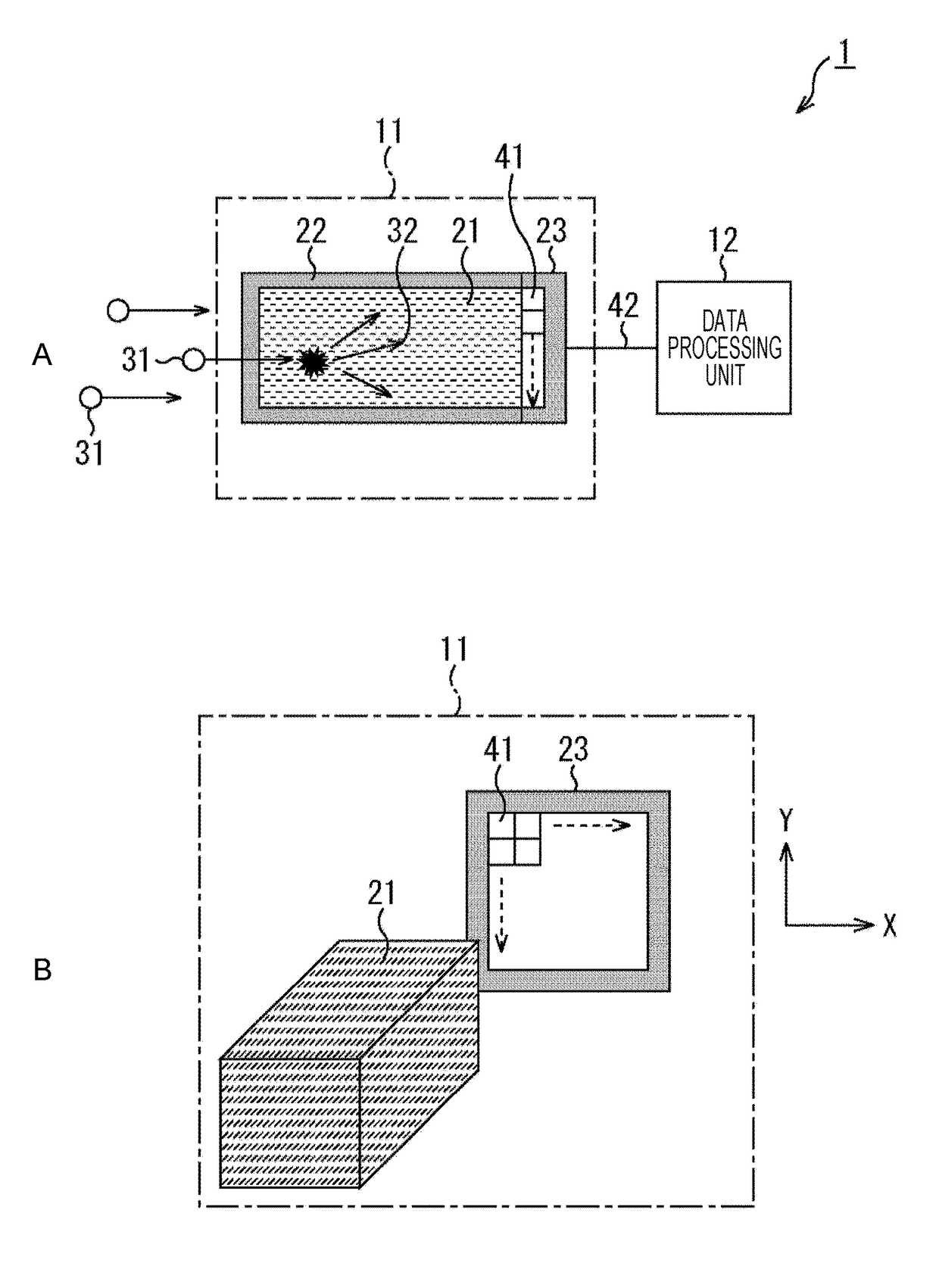
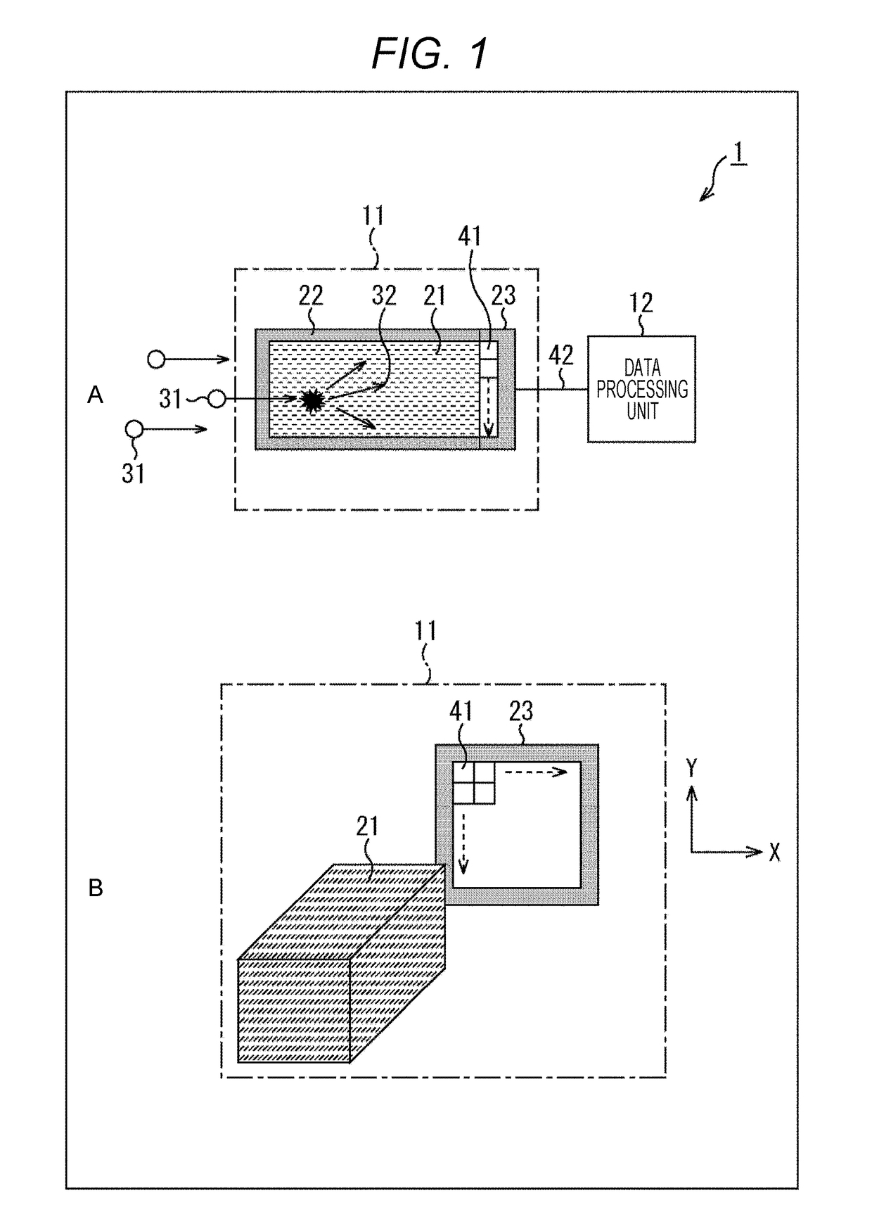
[0059]FIG. 1 illustrates a configuration example of a first embodiment of a radiation counter device to which the present technology is applied.

[0060]A radiation counter device 1 illustrated in FIG. 1 includes a light-receiving unit 11 and a data processing unit 12. The light-receiving unit 11 includes a scintillator 21, a partition wall 22, and an optical detector 23.

[0061]A of FIG. 1 illustrates a cross-sectional view of the scintillator 21, the partition wall 22, and the optical detector 23 of the light-receiving unit 11, and B of FIG. 1 illustrates a perspective view of the scintillator 21 and the optical detector 23 of the light-receiving unit 11.

[0062]When radiation 31 is incident to the scintillator 21, the scintillator 21 generates photons 32. For example, the scintillator 21 includes sodium iodide (NaI), and the size of a surface facing the optical detector 23 is processed into a rectangular parallelepi...

second embodiment

2. Second Embodiment

[0257]FIG. 24 illustrates a configuration example of a second embodiment of the radiation counter device to which the present technology is applied.

[0258]FIG. 24 is a perspective view of a radiation counter device 1 of the second embodiment which corresponds to B of FIG. 1.

[0259]In FIG. 24, the same reference numeral is given to a portion corresponding to the first embodiment, and description thereof is appropriately omitted.

[0260]As in the first embodiment, the radiation counter device 1 of the second embodiment also includes the light-receiving unit 11 and the data processing unit 12.

[0261]In the first embodiment, one scintillator 21 is correlated to the optical detector 23, and scintillation light is diffused to the entirety of the surface in the opening of the optical detector 23.

[0262]In contrast, the radiation counter device 1 of the second embodiment includes a scintillator array 121 including four scintillators 21-C1 to 21-C4 with respect to the optical d...


PUM


Abstract

The present technology relates to an optical pulse detection device, an optical pulse detection method, a radiation counter device, and a biological testing device which are capable of performing radiation counting in a more accurate manner. The optical pulse detection device includes a pixel array unit in which a plurality of pixels are arranged in a two-dimensional lattice shape, an AD converter that converts output signals of each of the pixels in the pixel array unit into digital values with gradation greater than 1 bit, and an output control circuit that performs error determination processing of comparing the digital value with a predetermined threshold value, and discarding a digital value, which is greater than the threshold value, among the digital values as an error. For example, the present technology is applicable to a radiation counter device, and the like.

Description


Claims


Application Information

Patent Timeline
Owner SONY SEMICON SOLUTIONS CORP
Why Eureka
Try Eureka