
Gate driving circuit and display device

a driving circuit and display device technology, applied in the direction of static storage, digital storage, instruments, etc., can solve problems such as image display error, and achieve the effect of reducing resistive-capacitive delays of scan signals inputted to the display panel, ensuring image display quality and stability

Active Publication Date: 2018-11-15
HANNSTAR DISPLAY CORPORATION
View PDF1 Cites 0 Cited by
  • Summary
  • Abstract
  • Description
  • Claims
  • Application Information

AI Technical Summary

Benefits of technology

The invention aims to improve the performance of gate driving circuits and display devices by reducing delays in scan signals. This helps to ensure better image display quality and stability.

Problems solved by technology

For a high-resolution display device, the charge time of each scan signal is relatively shorter, and the scan signals generated by first several stages of shift registers have longer resistive-capacitive delays, thus easily resulting in an image display error issue.

Method used


Image

  • Gate driving circuit and display device
  • Gate driving circuit and display device
  • Gate driving circuit and display device

Examples


Embodiment Construction

[0030]The detailed explanation of the invention is described as following. The described preferred embodiments are presented for purposes of illustrations and description, and they are not intended to limit the scope of the invention.

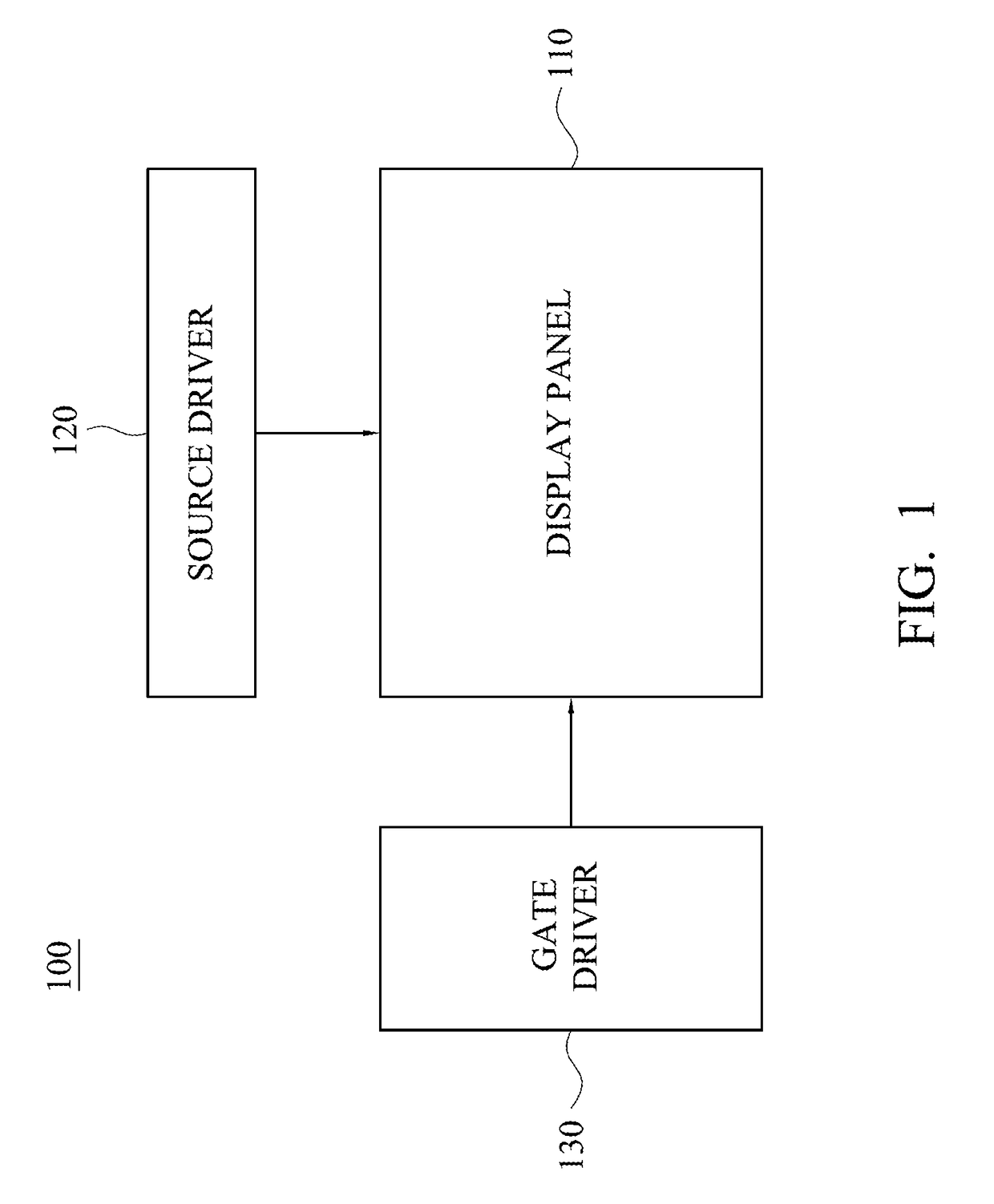
[0031]Referring to FIG. 1, which is a schematic diagram of a display device 100. The display device 100 includes a display panel 110, a source driver 120 and a gate driver 130. The display panel 110 includes pixels arranged in a matrix for collectively displaying an image. The display panel 110 may be, for example, a liquid crystal display (LCD) panel of twisted nematic (TN) mode, in-plane switching (IPS) mode, fringe-field switching (FFS) mode, vertical alignment (VA) mode or other different modes, or an organic light-emitting diode (OLED) display panel, but is not limited thereto. The source driver 120 is electrically connected to the display panel 110, and is configured to convert image data into source driving signals and transmit the source driving...


PUM


Abstract

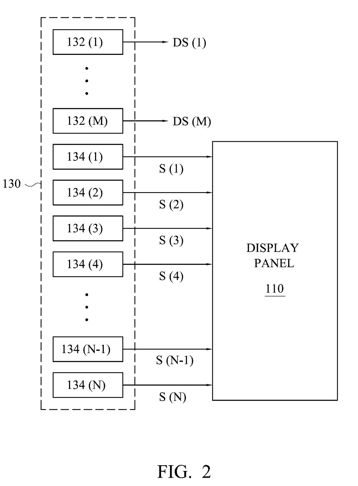
The invention provides a gate driving circuit and a display device. The gate driving circuit is configured to drive a display panel of the display device, and includes shift registers and at least a dummy shift register. The shift registers are respectively configured to generate and output scan signals to scan lines of the display panel, the dummy shift register is configured to generate a dummy scan signal before the scan signals are generated. The dummy scan signal and the scan signals are sequentially generated.

Description

RELATED APPLICATIONS[0001]This application is a continuation of the U.S. application Ser. No. 15 / 347,794, filed on Nov. 10, 2016, which claims the priority benefit of Chinese Application Serial Number 201610580994.8, filed on Jul. 22, 2016. All disclosures are incorporated herewith by reference.BACKGROUNDField of Invention[0002]The invention relates to a gate driving circuit and a display device, and more particularly to a gate driving circuit and a display device including dummy shift registers.Description of Related Art[0003]A flat panel display device, such as a liquid crystal display (LCD) device or an organic light-emitting diode (OLED) display device, generally has a lot of shift registers for controlling gray levels of all pixels displayed in the display device at the same time point. In addition, with advancing development technologies of thin film transistor (TFT) liquid crystal display, technologies of integrating a driving circuit (e.g. a gate driving circuit) on a displa...

Claims


Application Information

Patent Timeline
Patent Type & Authority Applications(United States)
IPC IPC(8): G09G3/20G11C19/28
CPCG11C19/287G09G2310/0286G09G3/2092G09G3/3674G09G2300/0809G09G3/3266G09G2320/0223
Inventor CHAN, CHIEN-TINGHSU, YU-TUANCHEN, PO-YI
Owner HANNSTAR DISPLAY CORPORATION
Learn More