
Pipe clamp pliers

Inactive Publication Date: 2018-11-22
HUO MENG TECH CO LTD
View PDF6 Cites 3 Cited by
  • Summary
  • Abstract
  • Description
  • Claims
  • Application Information

AI Technical Summary

Benefits of technology

The present invention provides a pair of pipe clamp pliers that make it easy to tighten and loosen the pipe clamp. The pliers can securely and firmly clamp the pipe clamp, which is designed to make assembly and maintenance faster and more efficient.

Problems solved by technology

However, the structure is not easy to operate.
Therefore, the operation is difficult and is not efficient.
However, the contact area is extremely small, so the pipe clamp may slip easily.

Method used


Image

  • Pipe clamp pliers
  • Pipe clamp pliers
  • Pipe clamp pliers

Examples


Embodiment Construction

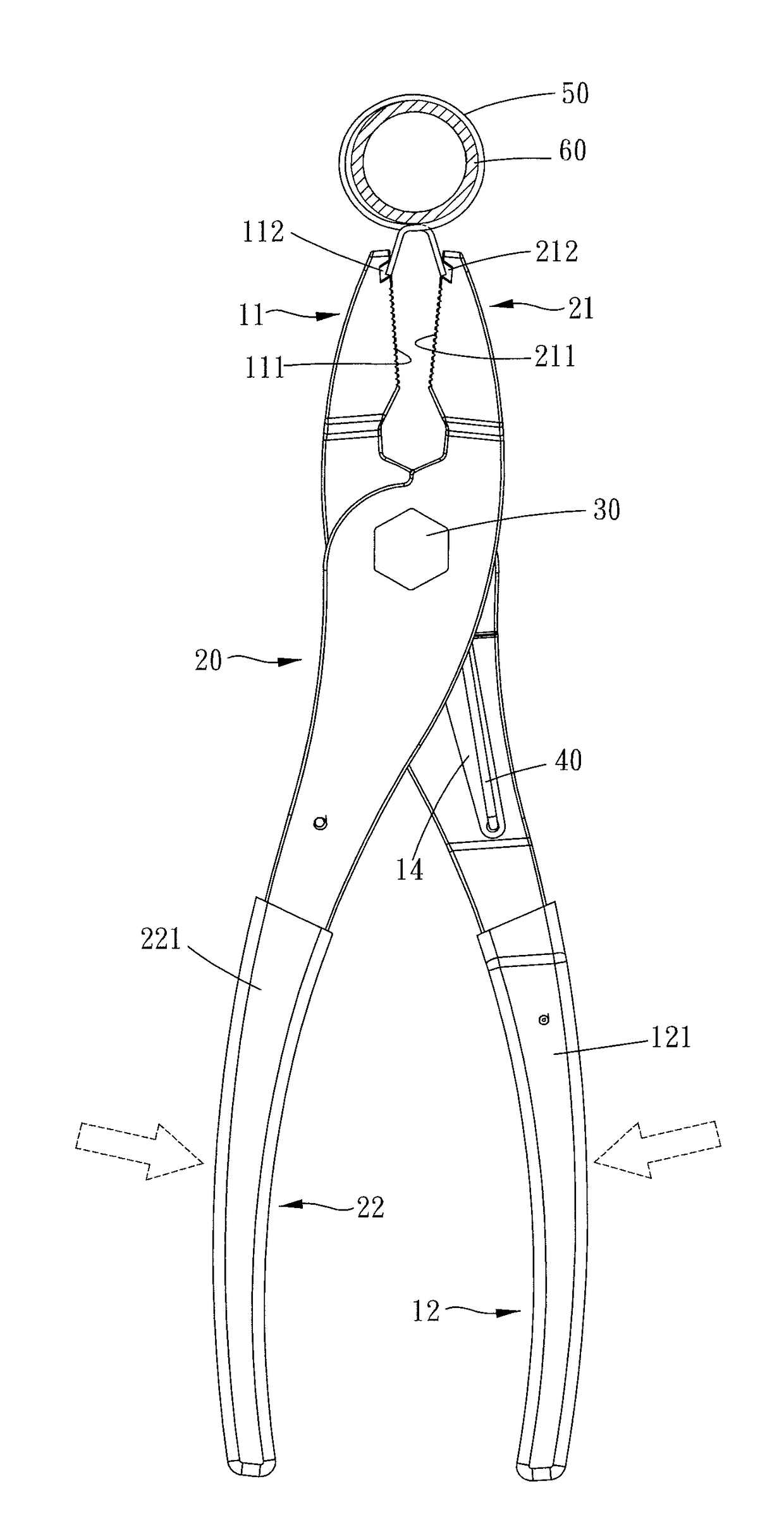
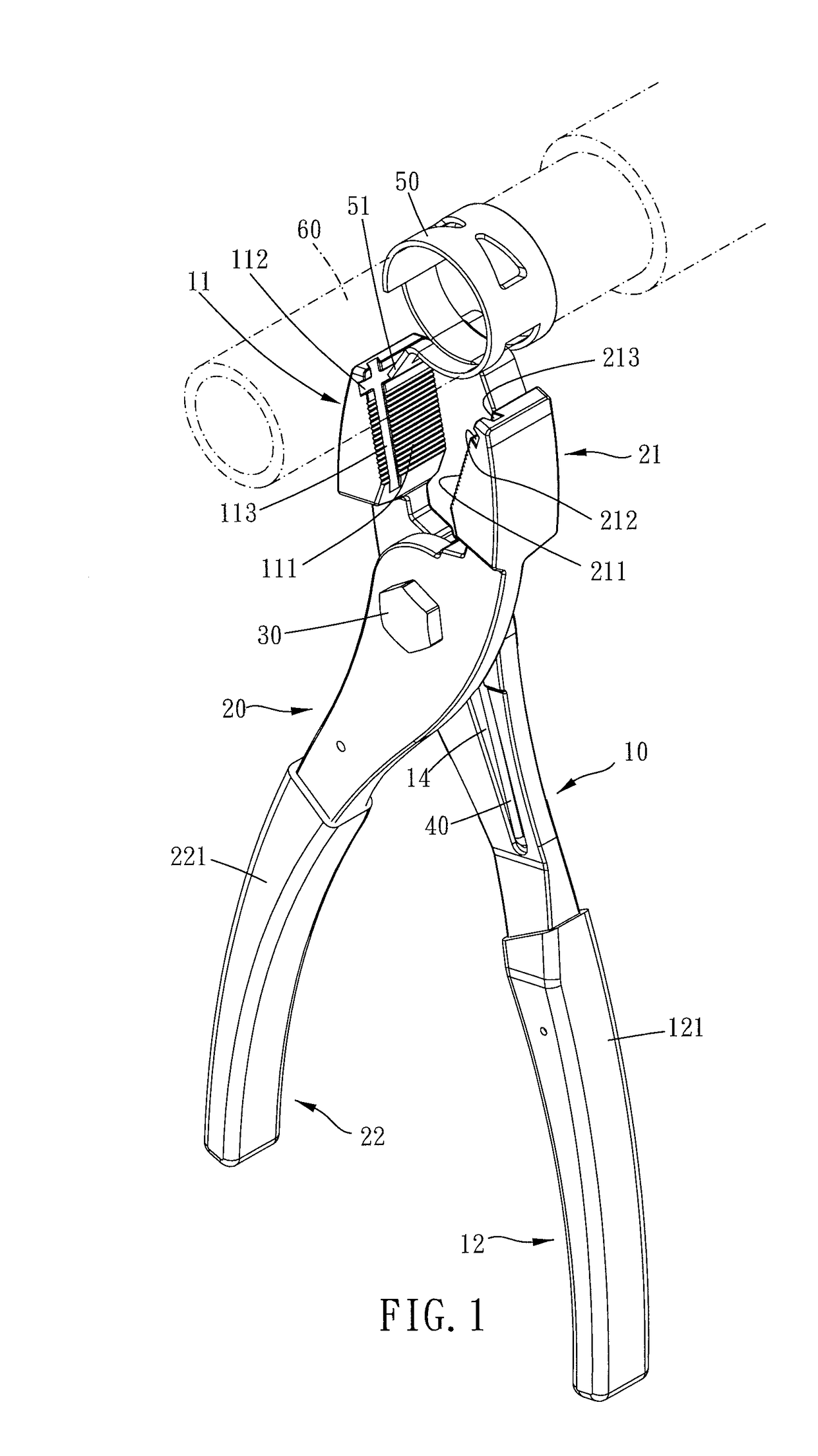
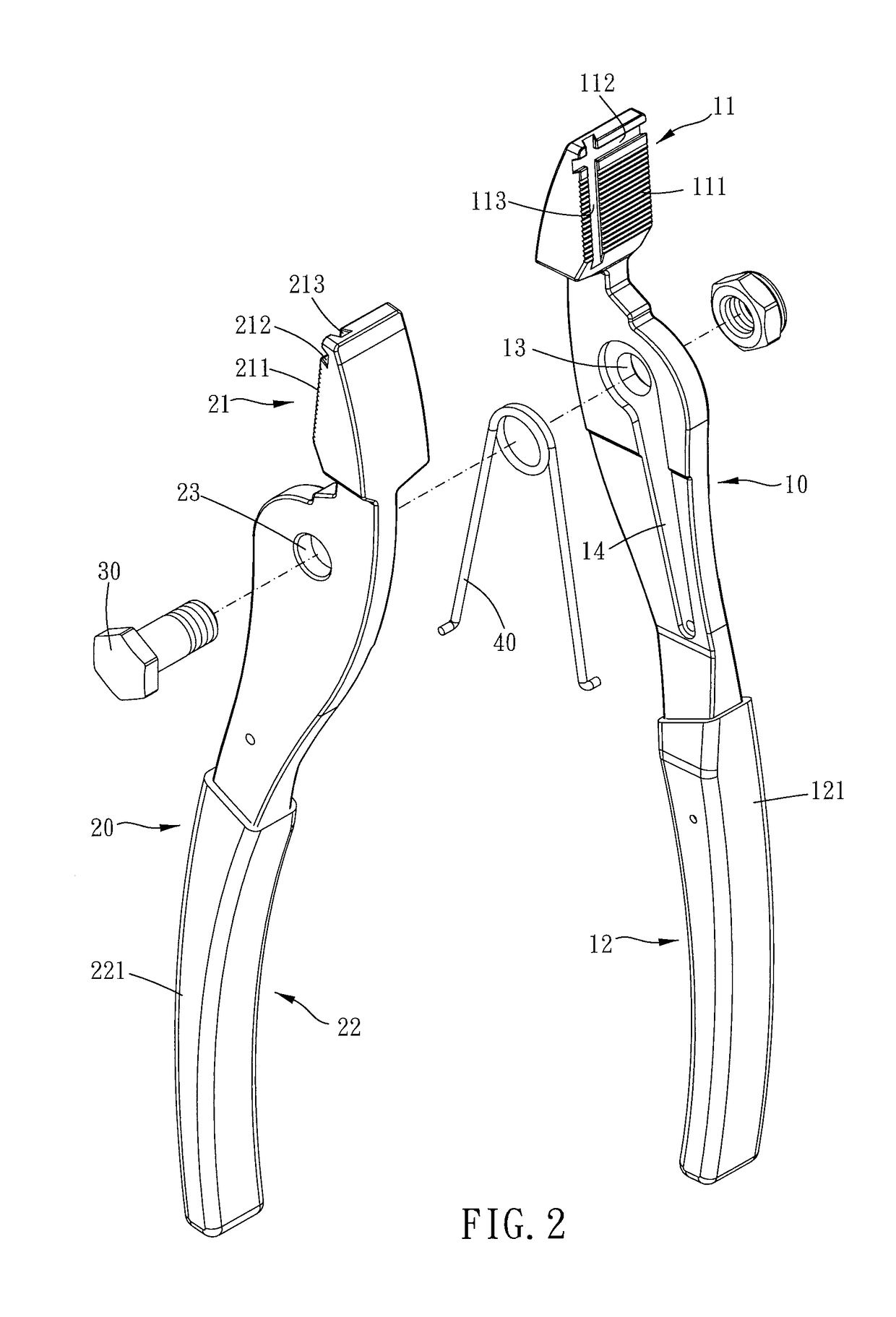
[0019]Please refer to FIGS. 1 to 6, FIG. 3A, and FIG. 3B, a pipe clamp pliers of the present invention includes a first clamping member 10 and a second clamping member 20.

[0020]The first clamping member 10 has a first end 11 and a second end 12. The first clamping member 10 further has a first pivot portion located between the first end 11 and the second end 12. A first clamping portion is provided at the first end 11. A first holding portion is provided at the second end 12. A first direction is defined as a direction that the first end 11 and the second end 12 are aligned.

[0021]The second clamping member 20 has a third end 21 and a fourth end 22. The second clamping member 20 further has a second pivot portion located between the third end 21 and the fourth end 22. The second pivot portion is pivotally connected with the first pivot portion. A second clamping portion is provided at the third end 21. A second holding portion is provided at the fourth end 22. A second direction is d...


PUM


Abstract

The pipe clamp pliers includes a first and a second clamping members. The first clamping member has a first and a second ends, and further has a first pivot portion between the first and the second ends. A first clamping portion is provided at the first end. The second clamping member has a third and a fourth ends, and further has a second pivot portion between the third and the fourth ends. A second clamping portion is provided at the third end. The second pivot portion is pivotally connected with the first pivot portion. The first and the second clamping portions are formed with a first and a second horizontal grooves. At least one of a corner of the first horizontal groove near the first pivot portion and a corner of the second horizontal groove near the second pivot portion is smaller than 90 degrees.

Description

BACKGROUND OF THE INVENTIONField of the Invention[0001]The present invention relates to a pipe clamp pliers.Description of the Prior Art[0002]A conventional pipe clamp pliers for loosening pipe clamp is shown in patent TW M287208. The pipe clamp pliers has a sliding sleeve having a fixed pushing element and a slidable pushing element. The slidable pushing element can be moved by a pliers. When the two leg portions of the pipe clamp abut against the two pushing elements respectively, the slidable pushing element is moved toward the fixed pushing element by pressing the pliers. Thus, the distance between the two leg portions is shortened, and the pipe clamp is loosened.[0003]However, the structure is not easy to operate. More specifically, the sliding sleeve and the pliers are independent from each other. Thus, a user has to be arrange the two pushing elements on the two leg portions of the pipe clamp first. And then, the user holds the sliding sleeve with one hand and operates the pl...

Claims


Application Information

Patent Timeline
IPC IPC(8): B25B25/00B25B7/02F16L33/025
CPCB25B25/005F16L33/025B25B7/02
Inventor LIU, CHAO-MIN
Owner HUO MENG TECH CO LTD
Learn More