Backlight unit and luminous flux control member for local dimming

a technology of luminous flux control and backlight unit, which is applied in the direction of instruments, optical light guides, optics, etc., to achieve the effect of suppressing the white-spot phenomenon and improving the ability of partially light extracting to suppress the shadow-ring phenomenon

Inactive Publication Date: 2018-11-22
SEOHAN LITEK CO LTD
View PDF9 Cites 34 Cited by
  • Summary
  • Abstract
  • Description
  • Claims
  • Application Information

AI Technical Summary

Benefits of technology

[0009]The inventive concept provides a luminous flux control member which can spreads light around the light axis of a light s

Problems solved by technology

Thus, for sufficiently uniform spreading of the light emitted from the LED over the light irradiation region and suppressing the white-spot phenomenon, the direct type backlight unit has a design limitat

Method used


Image

  • Backlight unit and luminous flux control member for local dimming
  • Backlight unit and luminous flux control member for local dimming
  • Backlight unit and luminous flux control member for local dimming

Examples


Embodiment Construction

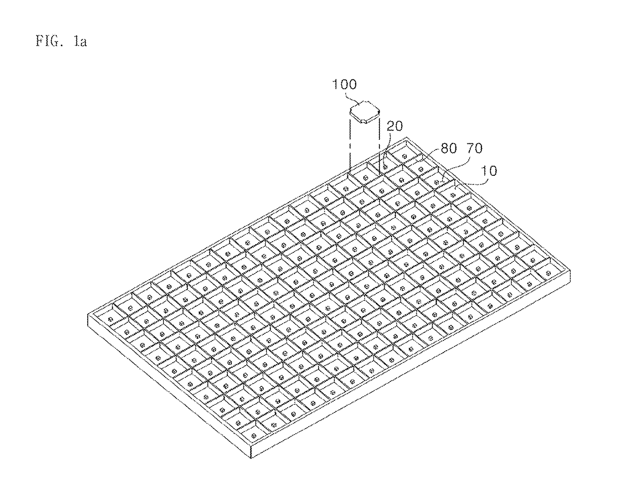
[0048]FIG. 1 is a perspective view illustrating a backlight unit according to an embodiment of the inventive concept.

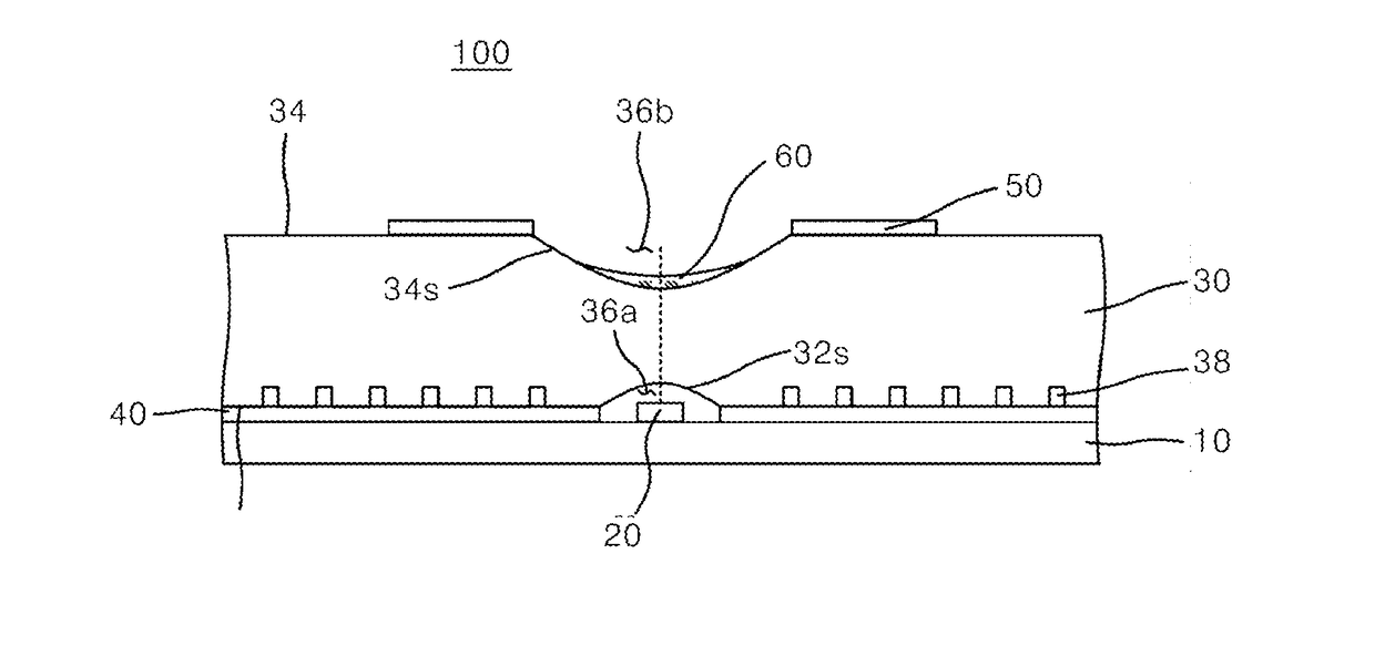
[0049]Referring to FIG. 1, the backlight unit may include a frame coupled with a rear surface of a LCD display panel. A substrate with a plurality of light sources 20 is disposed on the frame. Luminous flux control members 100 corresponding to the light sources are disposed on the substrate 10. The luminous flux control members 100 are respectively disposed over the light sources 200 such that light emitted from the light sources is transmitted through the luminous flux control member thereby spreading uniformly over entire surface of the backlight unit.

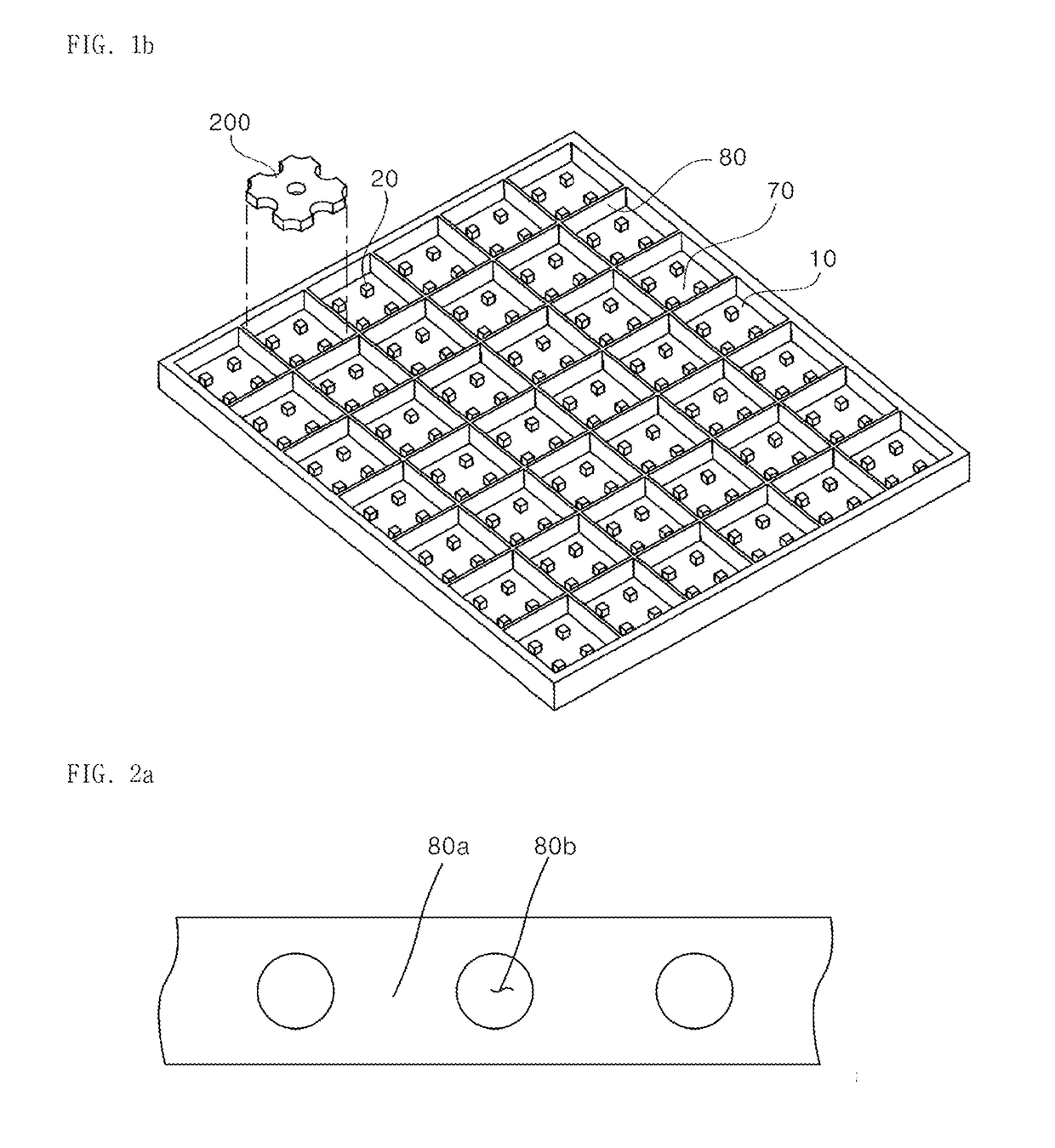
[0050]The substrate 10 is separated into a plurality of domains 70 such that the light sources 20 are disposed on the domains, respectively. A partition 80 is disposed on the substrate 10 to define the domains 70. The luminous flux control member 100 is disposed in each domain defined by the partition 80. The partition...


PUM


Abstract

A backlight unit is disclosed which is capable of diffusing light emitted from a light source uniformly and suppressing white spot phenomenon. The backlight unit includes a light guide panel having a first surface and a second surface opposite to the first surface, a concaved light receiving region formed on the first surface, a light intensity adjusting recess formed on the second surface, a light intensity adjusting sheet disposed on the light intensity adjusting recess and the second surface around the light intensity adjusting recess. The backlight unit includes a substrate on which a plurality of light emitting devices are disposed, a plurality of luminous flux control members which are disposed on the substrate corresponding to the light emitting devices such that the light from the light source is uniformly transmitted upward, and a shade layer which is disposed between the luminous flux control members to reflect a portion of the light emitted through the luminous flux control member.

Description

CROSS-REFERENCE TO RELATED APPLICATIONS[0001]This application is a continuation of International Application No. PCT / KR2018 / 002492 filed Feb. 2, 2018, which claims the benefit of Korean Patent Application No. 10-2017-0060902 filed May 17, 2017 and Korean Patent Application No. 10-2017-0073905 filed Jun. 13, 2017, each of which is expressly incorporated by reference herein in its entirety as if each were incorporated by reference herein individually.BACKGROUND1. Field[0002]The inventive concept relates to a backlight unit and a luminous flux control member for local dimming, and more specifically, to a backlight unit and a luminous flux control member for local dimming with wide light diffusion range.2. Description of Related Art[0003]In different to OLEDs capable of self-emitting, a display such as an LED incapable of self-emitting receives light using a backlight unit which is located behind the backside of the display.[0004]The backlight units using LEDs are classified into an edg...

Claims


Application Information

Patent Timeline
IPC IPC(8): F21V8/00
CPCG02B6/0038G02B6/0053G02B6/0055G02B6/0016G02B6/0036G02B6/0091G02B6/0021G02B6/0031
Inventor CHO, SEONGIK
Owner SEOHAN LITEK CO LTD
Why Eureka
Try Eureka