

Fly-by-wire mechanical control system
Patent Information
- Authority / Receiving Office
- US · United States
- Current Assignee / Owner
- SIKORSKY AIRCRAFT
- Publication Date
- 2018-11-29
- Estimated Expiration
- Not applicable · inactive patent
Smart Images
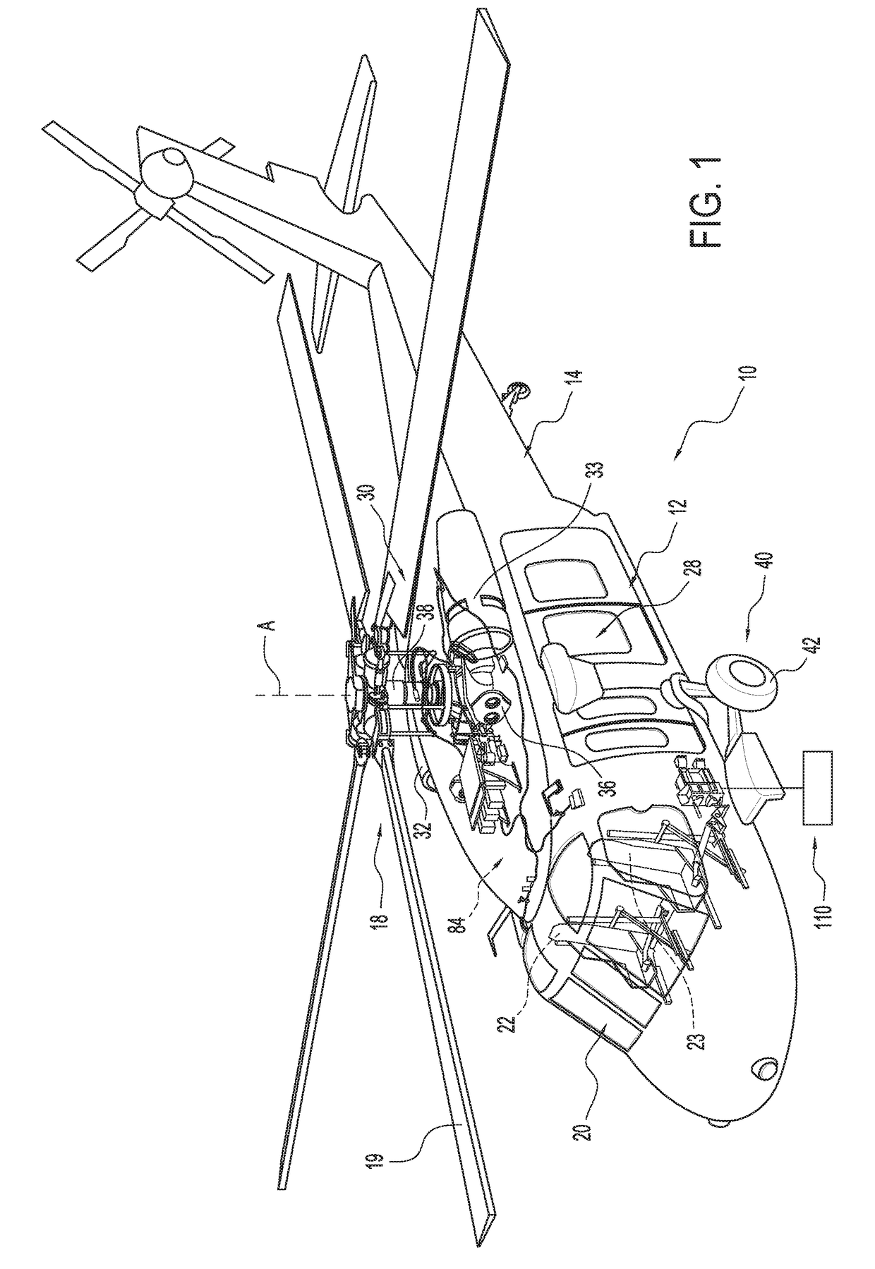
Figure 1 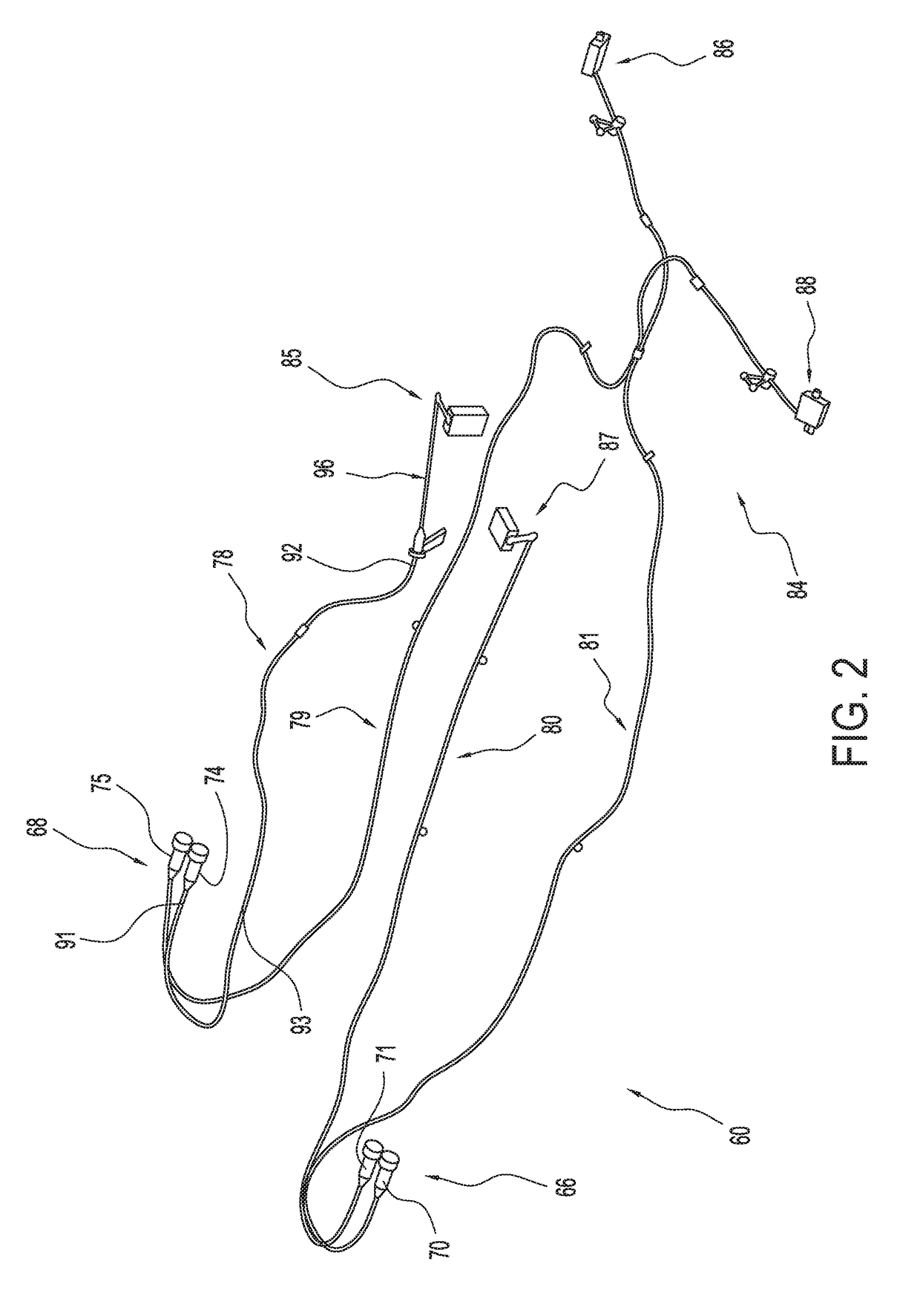
Figure 2 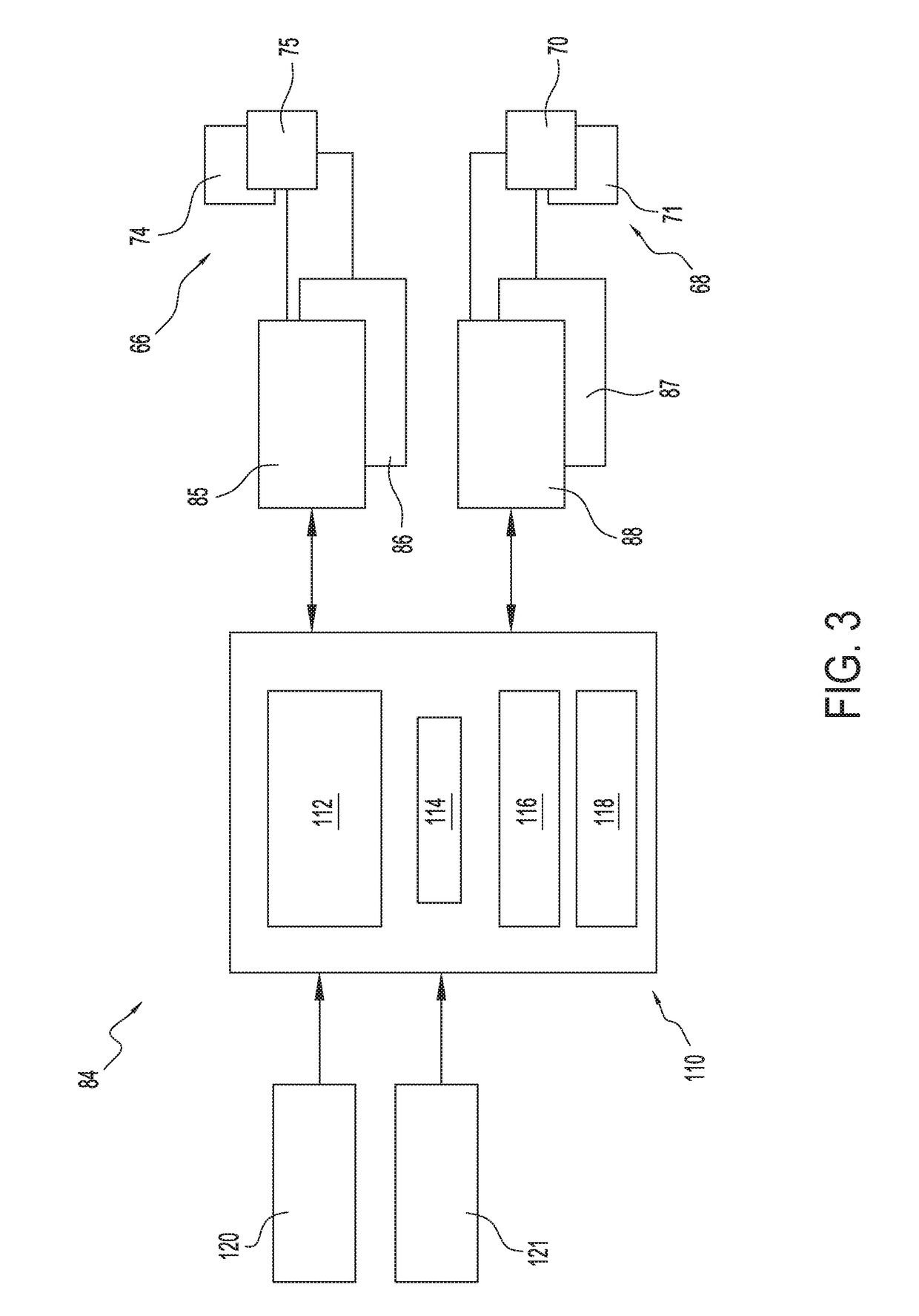
Figure 3
Abstract
Description
CROSS-REFERENCE TO RELATED APPLICATIONS
[0001] This application claims the benefit of U.S. Provisional Application Ser. No. 62 / 510,324, filed May 24, 2017, which is incorporated herein by reference in its entirety.STATEMENT OF FEDERAL SUPPORT
[0002] This invention was made with Government support under HR0011-15-9-0004 awarded by the Defense Advanced Research Projects Agency (DARPA). The Government has certain rights in the invention.BACKGROUND
[0003] Exemplary embodiments pertain to the art of vertical take-off and landing (VTOL) aircraft and, more particularly, to a fly-by-wire mechanical control system for a VTOL aircraft.
[0004] Conventional VTOL aircraft include control input mechanisms such as a collective, pedals, and a stick. Each of the control input mechanisms are coupled to controllable members, such as a rotor hub, engine control spindles, and the like through corresponding mechanical linkages. That is, there is a direct physical connection between the control input mechanisms a...