Aircraft provided with a buoyancy system, and a buoyancy method
- Summary
- Abstract
- Description
- Claims
- Application Information
AI Technical Summary
Benefits of technology
Problems solved by technology
Method used
Image

Examples
first embodiment
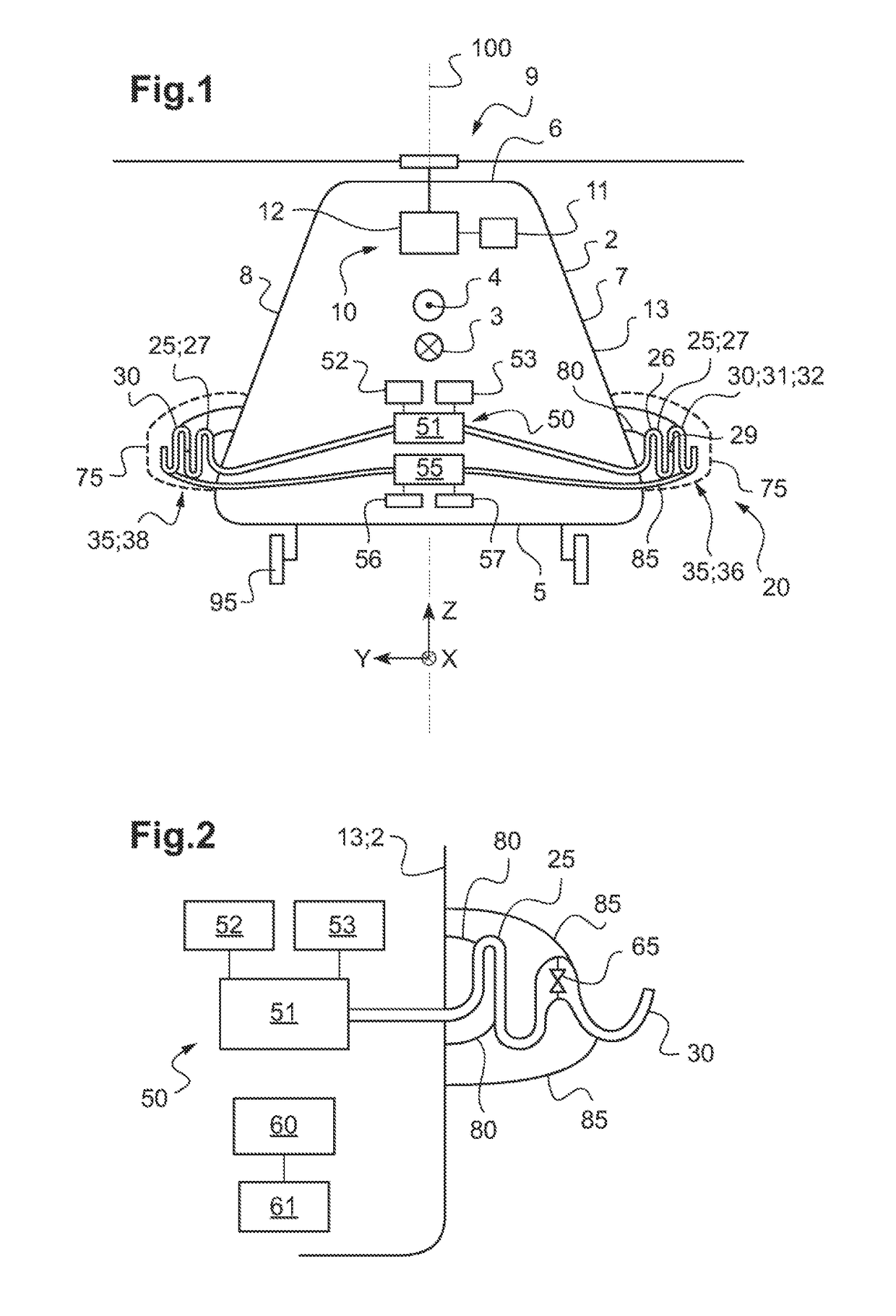
[0121]In FIG. 1, the deployment system 50 may include at least one inflater referred to for convenience as a “secondary” inflater 55. Each secondary inflater 55 is in fluid flow communication with at least one secondary float 30.
[0122]By way of example, a single secondary inflater 55 is connected to all of the secondary floats 30 via a plurality of pipes. In another example, the deployment system has as many secondary inflaters 55 as it has secondary floats 30, each secondary float 30 being connected by a pipe to an inflater that is specific thereto. In another example, two secondary inflaters 55 may be connected via at least one pipe to a single secondary float 30. Other configurations are naturally possible, it being possible for a single secondary inflater to inflate one or more secondary floats.
[0123]The deployment system may include a secondary control member 56 connected to each secondary inflater to control the operation of each secondary inflater. The term “secondary control...
second embodiment
[0128]In FIG. 2, no inflater is provided for directly inflating the secondary floats 30, i.e. without passing via a main float 25.
[0129]In this second embodiment, at least one main inflater 51 is thus connected by a pipe to at least one main float 25, each main float 25 being connected by a pipe to at least one main inflater 51.
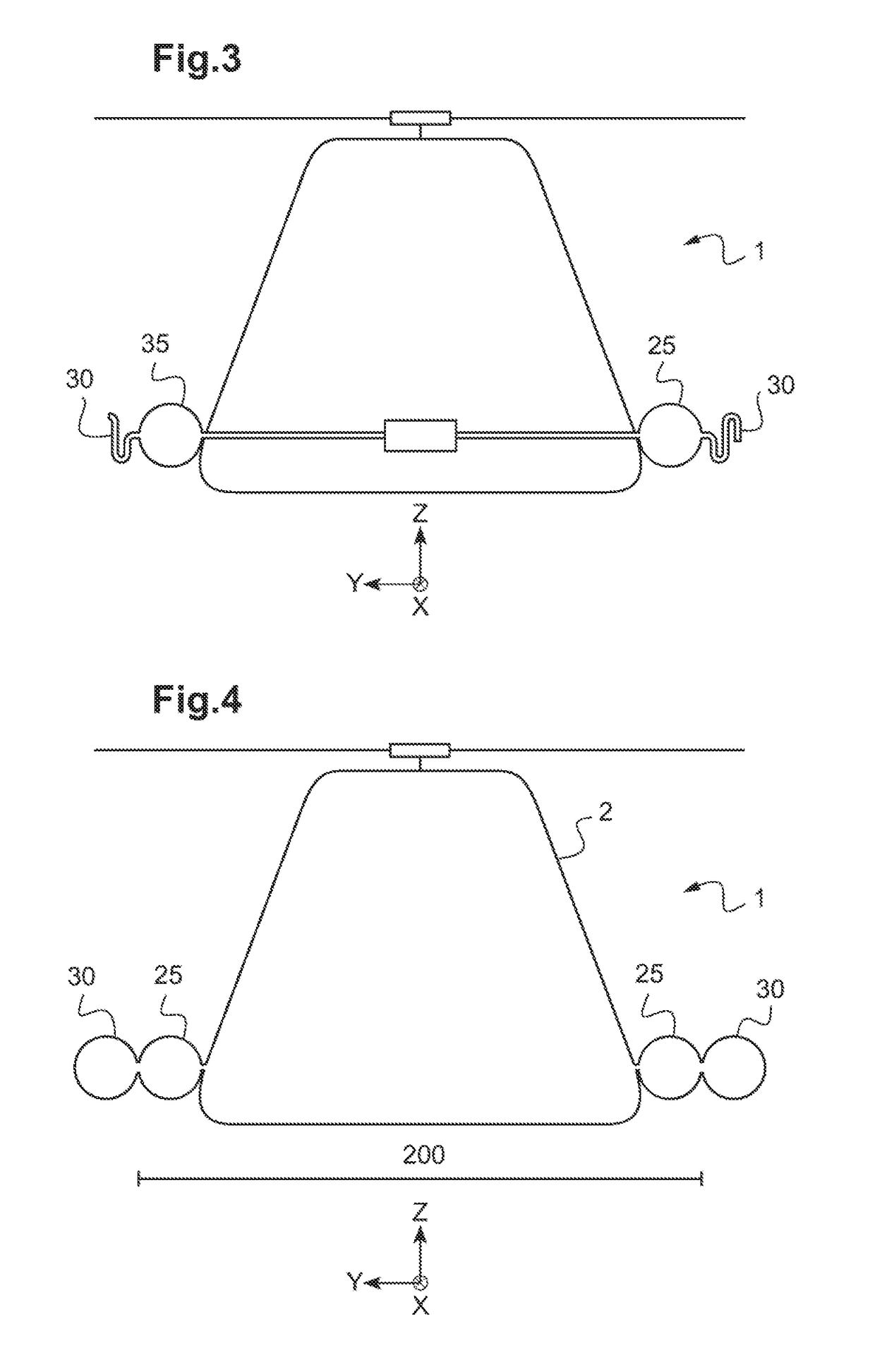
[0130]Furthermore, each secondary float 30 is connected to a main float 25 via a valve 65. For example, each secondary float 30 is connected to a single main float 25 via a valve, and each main float 25 is connected to a secondary float 30 via such a valve.
[0131]A valve 65 thus acts as an interface between a main inside volume of a main float and a secondary inside volume of a secondary float. When the valve is opened, some of the fluid contained in the main float fills the secondary float until an equilibrium position is reached. On equilibrium, the main float and the secondary float are both inflated. Where necessary, it is possible at this stage to top up ...
PUM
 Abstract
Description
Claims
Application Information
 - R&D
- Intellectual Property
- Life Sciences
- Materials
- Tech Scout
- Unparalleled Data Quality
- Higher Quality Content
- 60% Fewer Hallucinations
Browse by: Latest US Patents, China's latest patents, Technical Efficacy Thesaurus, Application Domain, Technology Topic, Popular Technical Reports.
© 2025 PatSnap. All rights reserved.Legal|Privacy policy|Modern Slavery Act Transparency Statement|Sitemap|About US| Contact US: help@patsnap.com