Auxiliary power system for rotorcraft with folding propeller arms and crumple zone loading gear

a technology of auxiliary power system and rotor system, which is applied in the direction of fuselage, transportation and packaging, and efficient propulsion technologies, etc., can solve the problems of low rotor speed, high aircraft loss, and inability to combine enough energy into the rotor system

Active Publication Date: 2018-12-06
MOOG INC
View PDF0 Cites 21 Cited by
  • Summary
  • Abstract
  • Description
  • Claims
  • Application Information

AI Technical Summary

Benefits of technology

[0011]The direct current bus is redundant in that even with a gas combustion engine failure the direct current bus battery pack will safely bring down the aircraft. The direct current bus is managed by a battery management system that ensures the battery pack is always charged. Once the battery management system senses that the gas combustion engine has failed, the main system flight controller will place the aircraft into emergency descent mode which will safely bring down the aircraft. One additional advantage of the direct current bus and gas combustion engine of various embodiments of this invention compared to other electrically driven rotorcraft is that once it lands, the rotorcraft is almost immediately ready for flight because the batteries are continuously charging and power is generated when the gas combustion engine is in operation.
[0013]The landing gear in one embodiment has five triangles on each side, including two center triangles which each have the apex of the triangle pointed downwardly. The bottom section of the landing gear that hits the ground first is longer than the top section that has three points attached to the fuselage. This design absorbs the energy of a hard landing.

Problems solved by technology

Thus, in the event of a main propulsion plant failure in a helicopter, rotor speed drops when power is no longer delivered to the rotor system.
Due to the limitations of prior art helicopter designs, sufficient energy cannot be coupled into the rotor system unless the helicopter is at or above a minimum altitude at the time of power failure.
A high proportion of aircraft loss is caused by loss or partial loss of the main propulsion system in the low and middle altitude zones followed by the inability of the helicopter to autorotate to an undamaged landing.

Method used


Image

  • Auxiliary power system for rotorcraft with folding propeller arms and crumple zone loading gear
  • Auxiliary power system for rotorcraft with folding propeller arms and crumple zone loading gear
  • Auxiliary power system for rotorcraft with folding propeller arms and crumple zone loading gear

Examples


Embodiment Construction

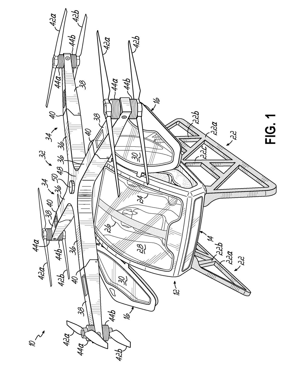
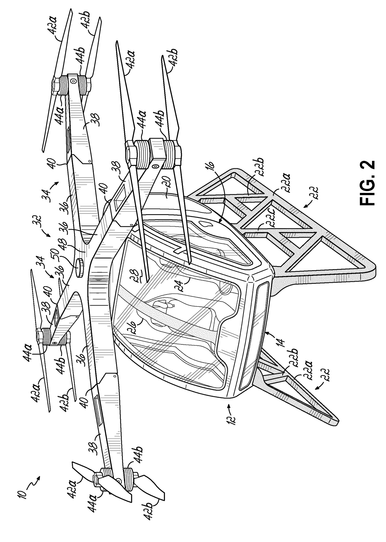
[0027]Referring to FIGS. 1 and 2, one embodiment of a rotorcraft 10 according to this invention is shown. The rotorcraft 10 includes a fuselage 12. The fuselage 12 includes a cockpit 14 which is accessible via a pair of cockpit doors 16 hingedly connected to either side of the fuselage 12. The fuselage 12 also includes a mechanical compartment 18 likewise accessible via a pair of hinged doors 20 (FIG. 2), one of which is on either side of the fuselage 12.

[0028]The rotorcraft 10 may also include a landing gear 22 supporting the fuselage 12 off the ground. In various embodiments, the landing gear 12 includes two skids positioned along either lateral side edge of the fuselage 12. The cockpit 14 may include a pilot seat 24 and a co-pilot or passenger seat 26 facing fowardly through a forward viewing window 28 on the fuselage 12. Windows 30 may also be included on the cockpit doors 16 for lateral viewing from the cockpit 14.

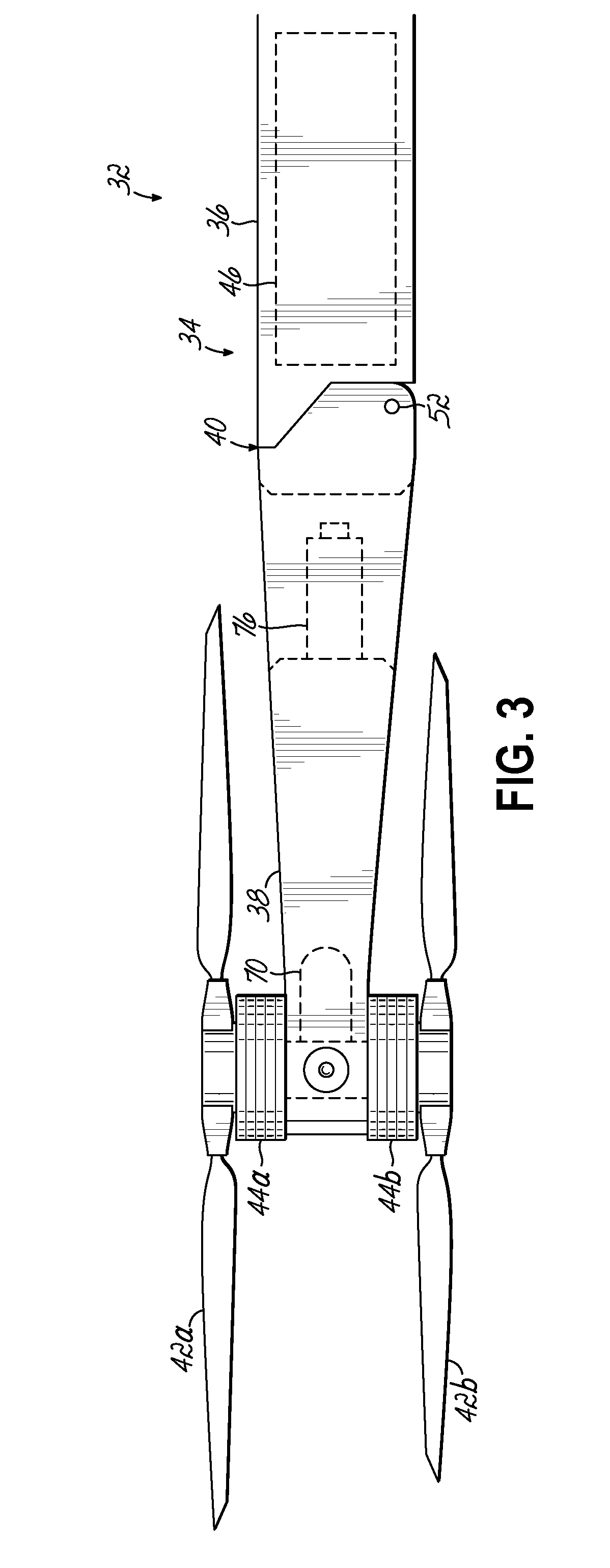
[0029]A rotor arm assembly 32 is mounted on top of the fuselage ...


PUM


Abstract

A vertical take-off and loading (VTOL) rotary aircraft or helicopter has eight propellers in a quad propeller arm configuration where each propeller arm has two counter-rotating propellers. Folding propeller arms are designed to allow storage in a single car sized garage. Each propeller may be powered by a three-phase alternating current motor. The main power plant for the aircraft is a gas combustion engine that generates electricity. If the gas engine fails, a battery backup system will safely bring the aircraft down for a controlled landing. The direct current bus is redundant in that even with a gas combustion engine failure the direct current bus battery pack will safely bring down the aircraft. Various embodiments of this invention may also include a landing gear crumple zone designed to soften a hard landing.

Description

[0001]This claims the benefit of US Provisional Application Ser. No. 62 / 513,677, filed Jun. 1, 2017 and hereby incorporated by reference in its entirety.BACKGROUND OF THE INVENTION[0002]This invention is in the field of rotary wing aircraft and in particular is for improving the safety and performance of a helicopter.[0003]The lift capacity of a helicopter is totally dependent upon the rotary movement of the rotor blades and a helicopter does not, per se, have any glide characteristics which typify many fixed wing aircraft. Thus, in the event of a main propulsion plant failure in a helicopter, rotor speed drops when power is no longer delivered to the rotor system. Lift developed by the rotor system is largely dependent upon rotor speed. At high enough altitudes, failure of the main propulsion plant will allow the pilot to successfully enter an autorotation mode wherein the descent of the helicopter is used to transfer power into the rotor system, thereby rotating the rotor blades, ...

Claims


Application Information

Patent Timeline
Patent Type & Authority Applications(United States)
IPC IPC(8): B64D27/24B64C27/10B64C1/06B64C25/52B64D27/08
CPCB64D27/24B64C27/10B64C1/063B64C25/52B64D27/08B64C2025/325B64D2027/026B64D2041/002B64D2221/00B64C27/08Y02T50/60
Inventor ARKUS, ALAN J.BURNS, STEPHEN S.CONNERS, PATRICKWEI, WEI
Owner MOOG INC
Why Eureka
Try Eureka