
Friction bolt

Active Publication Date: 2018-12-06
SANDVIK INTELLECTUAL PROPERTY AB
View PDF1 Cites 4 Cited by
  • Summary
  • Abstract
  • Description
  • Claims
  • Application Information

AI Technical Summary

Benefits of technology

The present invention provides a friction bolt assembly that prevents parts of the assembly from being ejected under high loads. This reduces the risk of injury and damage to equipment near the bolt. The technical effect of this invention is to increase safety and minimize the likelihood of damage caused by a friction bolt assembly in case of breakage.

Problems solved by technology

Insertion of the resin cartridge is sometimes very difficult, because typically the tunnel walls extend to a significant height, so that access to bores into which the cartridge is to be inserted can be inconvenient.
Additionally, the resin which is employed is relatively expensive and has a limited shelf life.
Cement grouted rock bolts are less expensive than resin anchored bolts, but application of the cement is more cumbersome than that of the resin.
Any form of rock bolt is susceptible to fail if the bolt is exposed to excessive loading by the rock strata into which the bolt has been installed.
Failure can be tensile or shear failure or it can be a combination of tensile and shear failure.
In expansion rock bolts, the bolt can fail through fracture of the tube.
However, if the rock bolt is loaded to the extent that both the tube and the bar (or cable) both fail, then there is the potential that a section of the rock bolt that is towards the open end of the bore (the trailing end of the rock bolt) can eject from the bore with considerable momentum, posing a danger to workers and equipment within the immediate vicinity.

Method used


Image

  • Friction bolt
  • Friction bolt
  • Friction bolt

Examples


Embodiment Construction

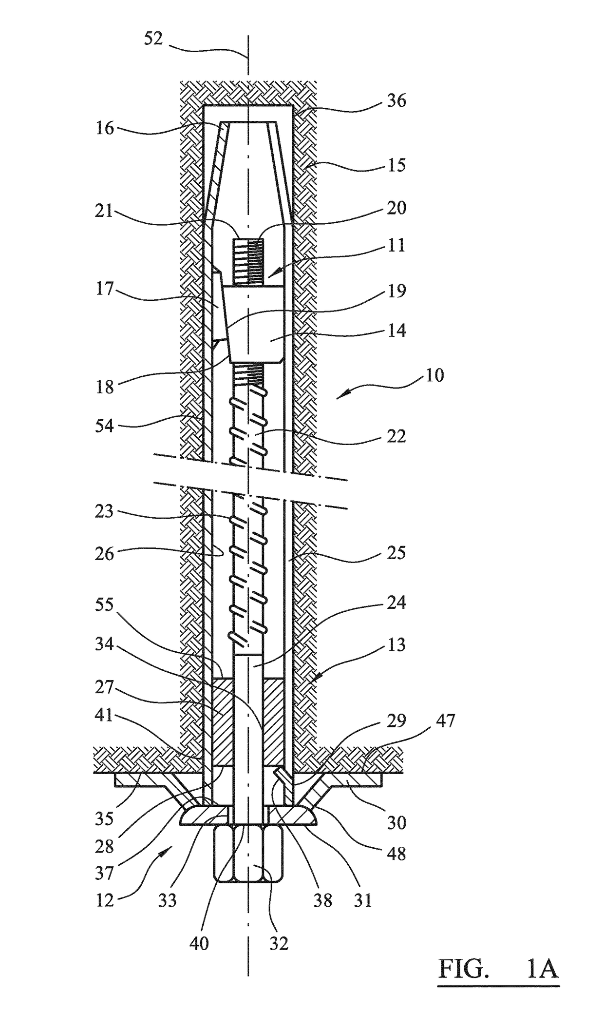
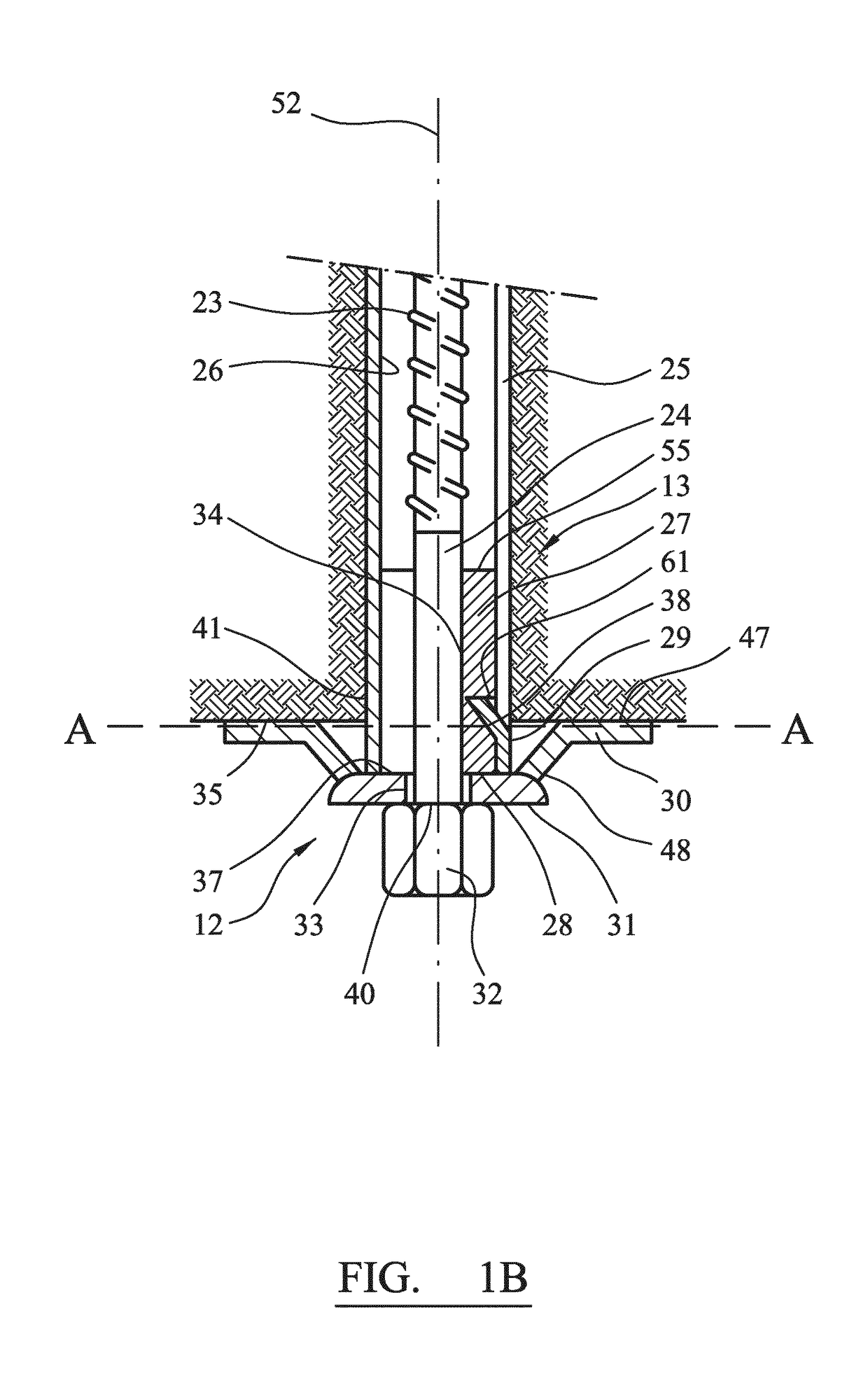
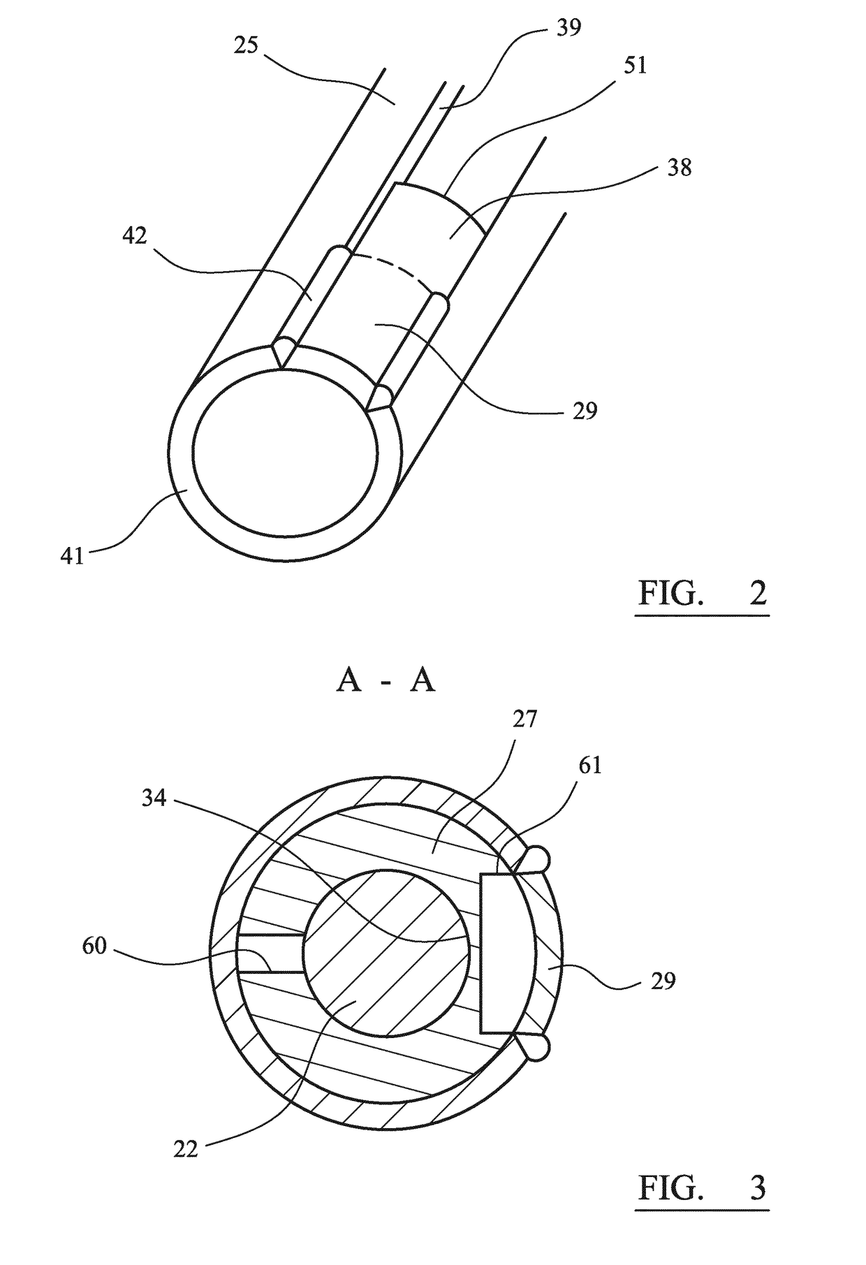
[0041]Referring to FIG. 1A, a friction rock bolt assembly 10 is configured for mounting and securement within a bore 36 extending within a rock strata 15. The friction bolt 10 is generally elongate being centred on longitudinal axis 52 and comprises primarily an elongate tube 25 that is split axially; an expander mechanism indicated generally by reference 11; a retainer mechanism indicated generally by reference 13 and an anchor mechanism indicated generally by reference 12. Expander mechanism 11 is mounted towards a leading end 16 of tube 25 whilst retainer mechanism 13 and anchor mechanism 12 are positioned towards a trailing end 41 of tube 25. In particular, anchor mechanism 12 projects rearwardly from tube 25 and is positioned at and extends from an open end of bore 36 adjacent a surface 35 of the rock strata 15 that surrounds the bore open end.

[0042]According to the specific implementation, expander mechanism 11 is formed from a pair of cooperating wedges 14, 17. A first wedge ...


PUM


Abstract

A friction bolt assembly to frictionally engage a bore formed in rock strata includes an elongate tube and an expander mechanism acted on by an anchor mechanism via an elongate bar or cable. A retainer mechanism is mounted to act between the bar or cable and the tube to prevent ejection of the bar or cable from the assembly should the bar or cable break.

Description

FIELD OF INVENTION[0001]The present invention relates to a friction bolt assembly for use in rock strata to stabilise the strata against fracture or collapse and in particular, although not exclusively, to a friction bolt configured to retain all components of the bolt within the assembly should parts of the bolt break in response to tensile and / or shear forces.BACKGROUND ART[0002]Expansion rock bolts are installed by drilling a bore into the rock strata, inserting the rock bolt into the bore and expanding the part of the bolt to provide a friction lock against the bore surface. Expansion rock bolts include an elongate tube, which is usually split longitudinally, with an expander mechanism positioned within the tube, normally towards the tube leading end that is inserted first into the drilled bore in the rock strata or wall. The expander mechanism is connected to a flexible cable or solid bar that extends to the trailing end of the bolt and attaches to an anchor such that expansion...

Claims


Application Information

Patent Timeline
IPC IPC(8): E21D21/00
CPCE21D21/004E21D21/0033E21D21/008E21D21/0086E21D21/0026E21D21/006
Inventor RATAJ, MIECZYSLAWYOUNG, PETERDARLINGTON, BRADLEY
Owner SANDVIK INTELLECTUAL PROPERTY AB
Learn More