Engine test stand mounting apparatus and method

a technology for testing stands and engines, applied in the direction of machines/engines, apparatus for force/torque/work measurement, instruments, etc., can solve the problems of unsatisfactory fidelity of load and vibration characteristics experienced by engines in testing

Active Publication Date: 2018-12-06
GENERAL ELECTRIC CO
View PDF0 Cites 8 Cited by
  • Summary
  • Abstract
  • Description
  • Claims
  • Application Information

AI Technical Summary

Benefits of technology

[0007]This problem is addressed by a providing a compliant engine test stand mounting adapter having multiple degrees of freedom, with the stiffness in each degree of freedom being substantially independent from that of the other degrees of freedom.
[0008]According to one aspect of the technology described herein, a compliant mounting adapter for mounting an engine to a test stand, includes: a body having: a first mounting interface configured for being coupled to the test stand; a second mounting interface configured for being coupled to the engine, the second mounting interface spaced-away from the first mounting interface; and a spanning element interconnecting the first and second mounting interfaces. The body is sufficiently flexible so as to permit relative movement of the two mounting interfaces, in response to forces generated by engine operation, in at least two degrees of freedom, and has a predetermined stiffness in each of the at least two degrees of freedom, the predetermined stiffness of each degree of freedom being substantially independent from the stiffness of the other degrees of freedom.
[0009]According to another aspect of the technology described herein, an engine testing apparatus includes: a test stand having a rigid vertical support column with a first end fixedly joined to a stationary foundation, and a second end having a rigid head frame fixedly joined thereto; one or more rigid mounting components configured to mechanically couple an engine to the head frame; and a compliant mounting adapter mechanically coupled to one of the rigid mounting components, the compliant mounting adapter having: a body including: a first mounting interface mechanically coupled to the test stand; a second mounting interface spaced-away from the first mounting interface; and a spanning element interconnecting the first and second mounting interfaces. The body is sufficiently flexible so as to permit relative movement of the two mounting interfaces, in response to forces generated by engine operation, in at least two degrees of freedom, and has a predetermined stiffness in each of the at least two degrees of freedom, with the predetermined stiffness of each degree of freedom being substantially independent from the stiffness of the other degrees of freedom.

Problems solved by technology

One problem with this arrangement is that the test stand itself and the test stand adapter are rigid structures having a spring constant much greater than that of the stiffness of the airframe (e.g. wing and / or pylon).
Therefore, the loads and vibration characteristics experienced by the engine in testing does not have perfect fidelity.

Method used


Image

  • Engine test stand mounting apparatus and method
  • Engine test stand mounting apparatus and method
  • Engine test stand mounting apparatus and method

Examples


Embodiment Construction

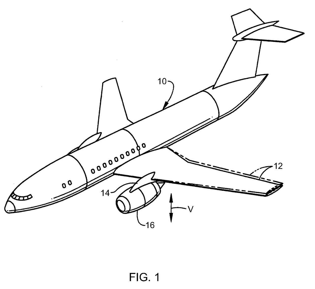
[0020]Now, referring to the drawings wherein identical reference numerals denote the same elements throughout the various views, FIG. 1 depicts an exemplary aircraft 10 having a wing 12 which includes a conventional pylon 14 supporting a conventional turbofan aircraft gas turbine engine 16.

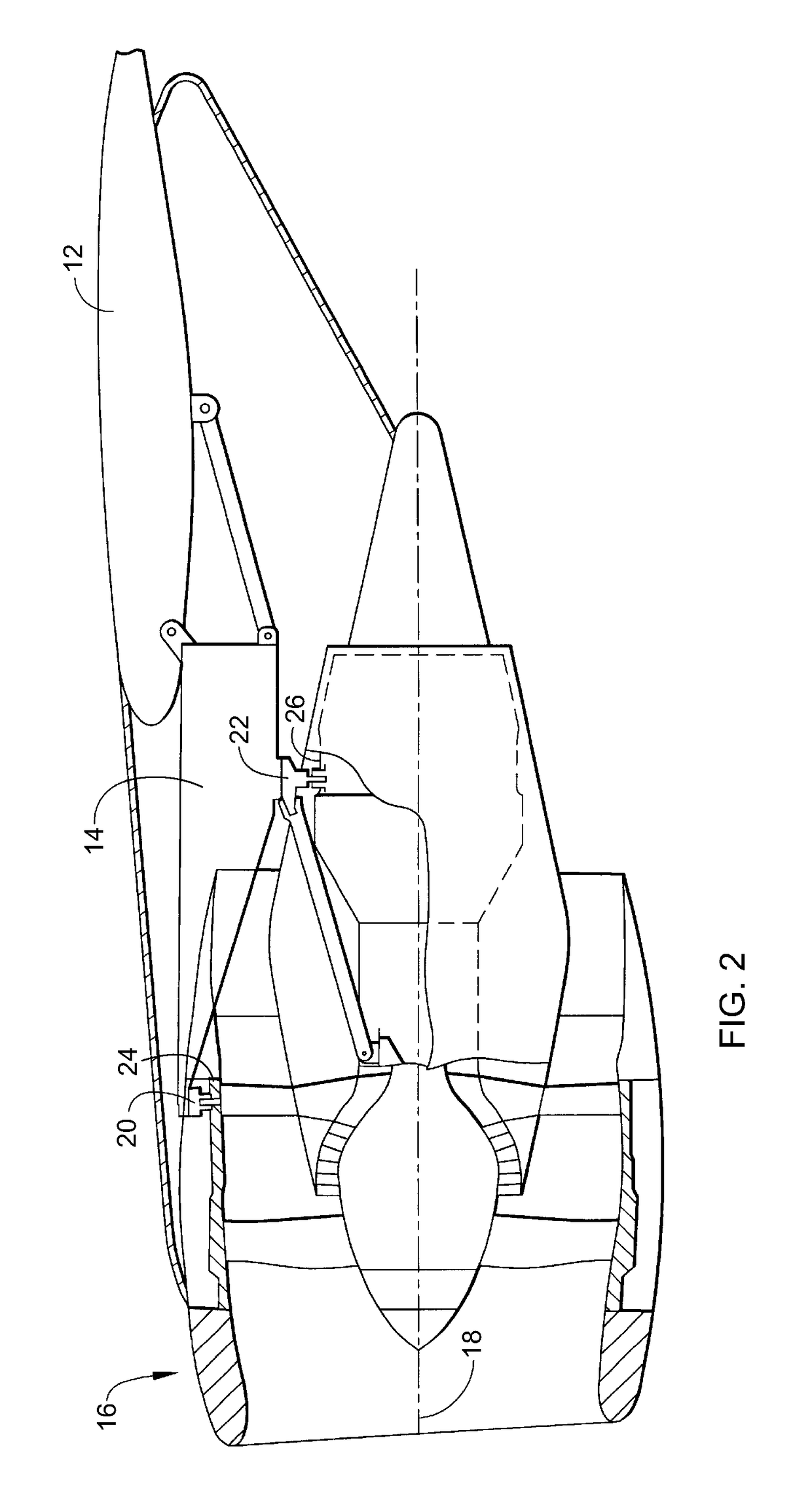
[0021]FIG. 2 shows the structure of the pylon 14 and the engine 16 in more detail. The engine 16 has a longitudinal or axial centerline axis 18 and is mounted to the pylon 14 at a forward mount 20 and an aft mount 22 spaced axially downstream from the forward mount 20. The forward mount 20 is joined to an annular fan casing 24. The aft mount 22 is joined to an annular engine casing 26 or some other stationary engine structure. The forward mount 20 and the aft mount 22 are joined to the pylon 14 by conventional means such as bolts, and the pylon 14 is in turn joined to the wing 12.

[0022]The wing 12 and pylon 14 combined have inherent flexibilities, for example as shown by the vertical movement ther...


PUM

PropertyMeasurementUnit
stiffnessaaaaaaaaaa
perimeteraaaaaaaaaa
thicknessaaaaaaaaaa

Abstract

A compliant mounting adapter for mounting an engine to a test stand includes: a body having: a first mounting interface configured for being coupled to the test stand; a second mounting interface configured for being coupled to the engine, the second mounting interface spaced-away from the first mounting interface; and a spanning element interconnecting the first and second mounting interfaces. The body is sufficiently flexible so as to permit movement relative movement of the two mounting interfaces, in response to forces generated by engine operation, in at least two degrees of freedom, and has a predetermined stiffness in each of the at least two degrees of freedom, with the predetermined stiffness of each degree of freedom being substantially independent from the stiffness of the other degrees of freedom.

Description

BACKGROUND OF THE INVENTION[0001]The present invention relates generally to engine testing, and more specifically, to a stationary test stand for supporting an aircraft gas turbine engine during power testing.[0002]Aircraft gas turbine engines include various rotors having blades rotating therewith such as fan, compressor, and turbine blades which generate vibratory excitation forces during operation. Accordingly, the engine is conventionally designed to maximize the margin between the various operational excitation frequencies and the critical frequencies associated with the natural resonance modes of vibration to minimize undesirable vibration and to obtain acceptable engine life.[0003]The vibratory response of the engine is typically affected by its supporting structure in the aircraft. For example, an aircraft engine is typically mounted to an aircraft wing by a conventional pylon. The combination of the aircraft wing and pylon have inherent flexibilities in each of the six spat...

Claims


Application Information

Patent Timeline
Patent Type & Authority Applications(United States)
IPC IPC(8): F01D25/28B64F5/60G01L5/13G01H1/00
CPCF01D25/285G01H1/003G01L5/133B64F5/60G01M15/04F05D2260/12F05D2260/83Y02T50/60
Inventor SCHMIDT, RICHARD
Owner GENERAL ELECTRIC CO
Why Eureka
Try Eureka