Engine test stand device

A technology of bracket device and engine, which is applied in the direction of engine test, measurement device, machine/structural component test, etc., can solve problems such as low efficiency, easy damage to engine bracket and dial indicator, and uncontrollable force, so as to avoid damage. , Reduce the amount of manual labor, the effect of high adjustment efficiency

Active Publication Date: 2013-12-18
ZHEJIANG GEELY AUTOMOBILE RES INST CO LTD +1
View PDF7 Cites 7 Cited by
  • Summary
  • Abstract
  • Description
  • Claims
  • Application Information

AI Technical Summary

Problems solved by technology

[0003] There are two problems in the centering of the traditional engine test bracket: 1. The test bracket is continuously hit with a hammer during alignment, causing serious deformation and damage to the test bracket; 2. The detection end of the dial indicator is used during alignment Stick it on the end surface of the engine flywheel and the shaft surface, and observe the reading of the dial indicator by hitting the test bracket with a hammer. However, when the hammer hits the test bracket, the force is uncontrollable, and sometimes too much force causes the vibration amplitude at the head of the meter to be too large and damage the dial indicator.
Therefore, the centering method of the traditional engine on the test bracket not only affects the test time, but also easily damages the engine bracket and dial indicator, which has a large amount of manual labor, affects the test progress of the engine, and has low efficiency

Method used


Image

  • Engine test stand device
  • Engine test stand device
  • Engine test stand device

Examples


Embodiment Construction

[0013] In order to further explain the technical means and effects adopted by the present invention to achieve the intended invention purpose, the specific implementation, structure, features and effects of the present invention will be described in detail below in conjunction with the accompanying drawings and preferred embodiments.

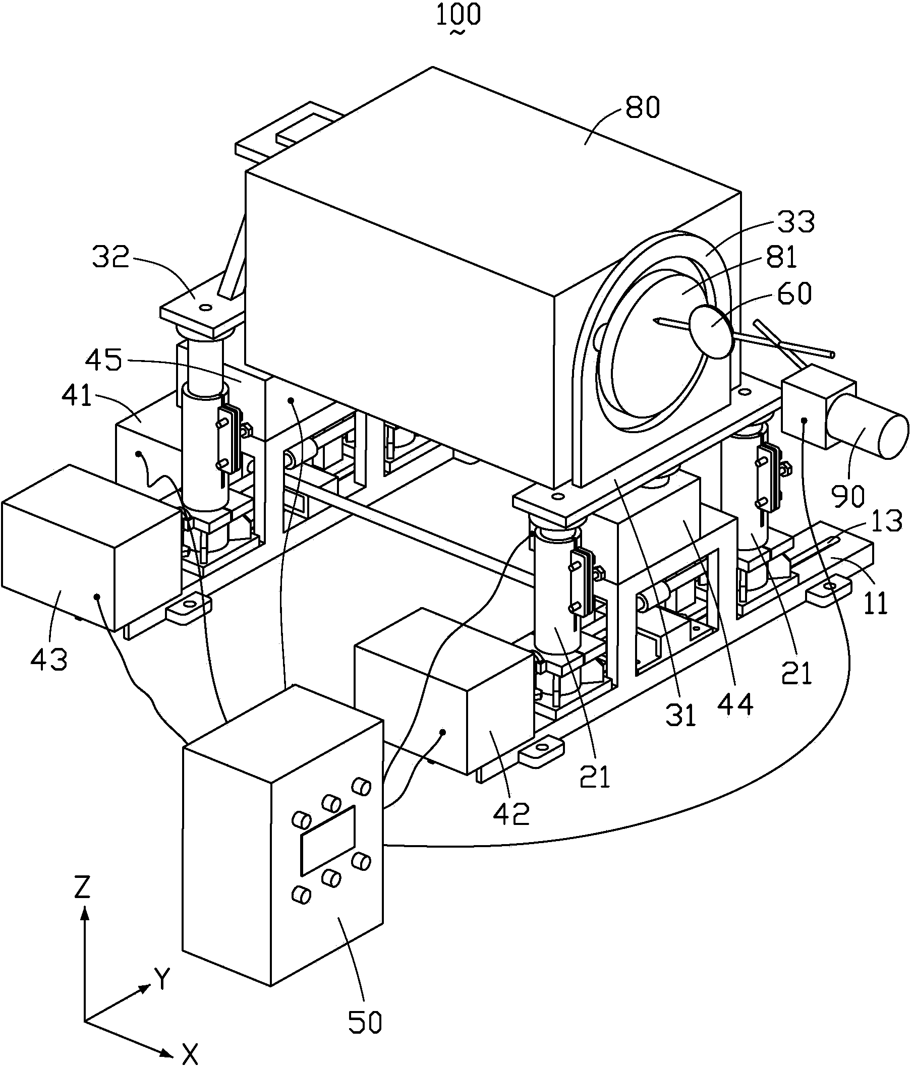
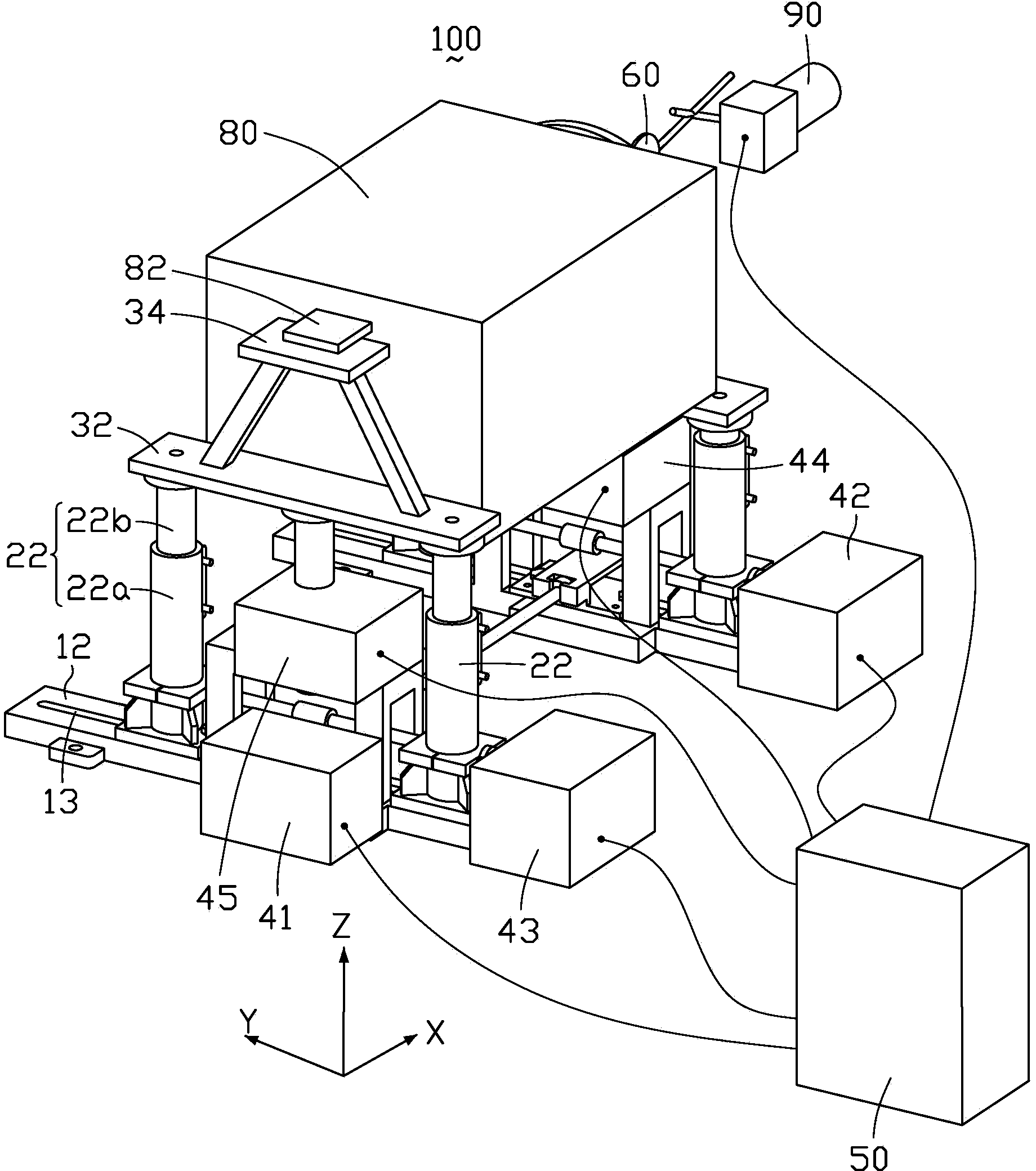
[0014] Please refer to figure 1 and figure 2 The engine test support device 100 provided by the embodiment of the present invention comprises a front support base 11, a rear support base 12, a first support 21, a second support 22, a front support top plate 31, a rear support top plate 32, a front and rear automatic adjustment mechanism 41, a front end Left and right automatic adjustment mechanism 42, rear end left and right automatic adjustment mechanism 43, front end up and down automatic adjustment mechanism 44, rear end up and down automatic adjustment mechanism 45, control box 50 and detection sensor 60.

[0015] The front support base 11...


PUM


Abstract

The embodiment of the invention discloses an engine test stand device. The engine test stand device comprises a front stand base, a rear stand base, a first supporting column, a second supporting column, a front stand top board, a rear stand top board, a front-and-back automatic adjusting mechanism, a front end left-and-right automatic adjusting mechanism, a rear end left-and-right automatic adjusting mechanism, a front end up-and-down automatic adjusting mechanism, a rear end up-and-down automatic adjusting mechanism, a control cabinet and a detection sensor. The detection sensor is used for detecting the end surface flatness and radial coaxiality, relative to a dynamometer, of an engine flywheel, and transmitting the detection data to the control cabinet. The control cabinet analyzes and processes the detection data and then transmits corresponding adjusting commands to the front-and-back automatic adjusting mechanism, the front end left-and-right automatic adjusting mechanism, the rear end left-and-right automatic adjusting mechanism, the front end up-and-down automatic adjusting mechanism and the rear end up-and-down automatic adjusting mechanism.

Description

technical field [0001] The invention relates to an automobile test bracket device, in particular to an engine test bracket device. Background technique [0002] When the engine is tested on the bench, the engine should be installed on the test bench bracket, and the flywheel end of the engine should be aligned in the plane and radial direction to ensure that the engine is positioned on the bracket and runs stably. In traditional alignment, first loosen the fastening nuts on the test bracket, and adjust the position of the engine by hitting a certain position on the bracket with a hammer, so that the radial runout of the flywheel end is within 0.3mm, and the runout of the end surface is within 0.2mm. [0003] There are two problems in the centering of the traditional engine test bracket: 1. The test bracket is continuously hit with a hammer during alignment, causing serious deformation and damage to the test bracket; 2. The detection end of the dial indicator is used during a...

Claims


Application Information

Patent Timeline
Patent Type & Authority Applications(China)
IPC IPC(8): G01M15/02G05D3/12
Inventor 杨辅新洪武白双全刘胜利沈源由毅冯擎峰
Owner ZHEJIANG GEELY AUTOMOBILE RES INST CO LTD
Why Eureka
Try Eureka