Laser Rangefinder Based Automatic Target Detection

a rangefinder and automatic detection technology, applied in the field of automatic detection of targets, can solve problems such as nois

Active Publication Date: 2018-12-06
TALON PRECISION OPTICS LLC
View PDF1 Cites 4 Cited by
  • Summary
  • Abstract
  • Description
  • Claims
  • Application Information

AI Technical Summary

Problems solved by technology

In some instances, ambient light may be received by the optical sensor circuitry of the laser rangefinder circuit and may represent noise.
Further, the emitted beam may diverge along a range or distance between the laser rangefinder device and the irradiated view area, such that the beam may partially overlap an object within the view area.

Method used


Image

  • Laser Rangefinder Based Automatic Target Detection
  • Laser Rangefinder Based Automatic Target Detection
  • Laser Rangefinder Based Automatic Target Detection

Examples


Embodiment Construction

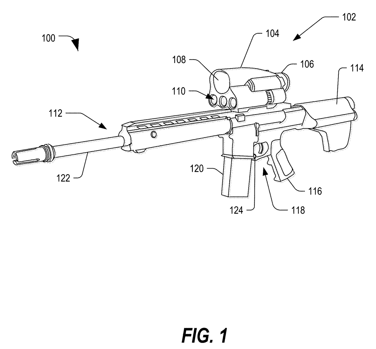
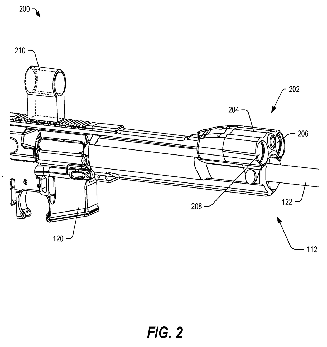
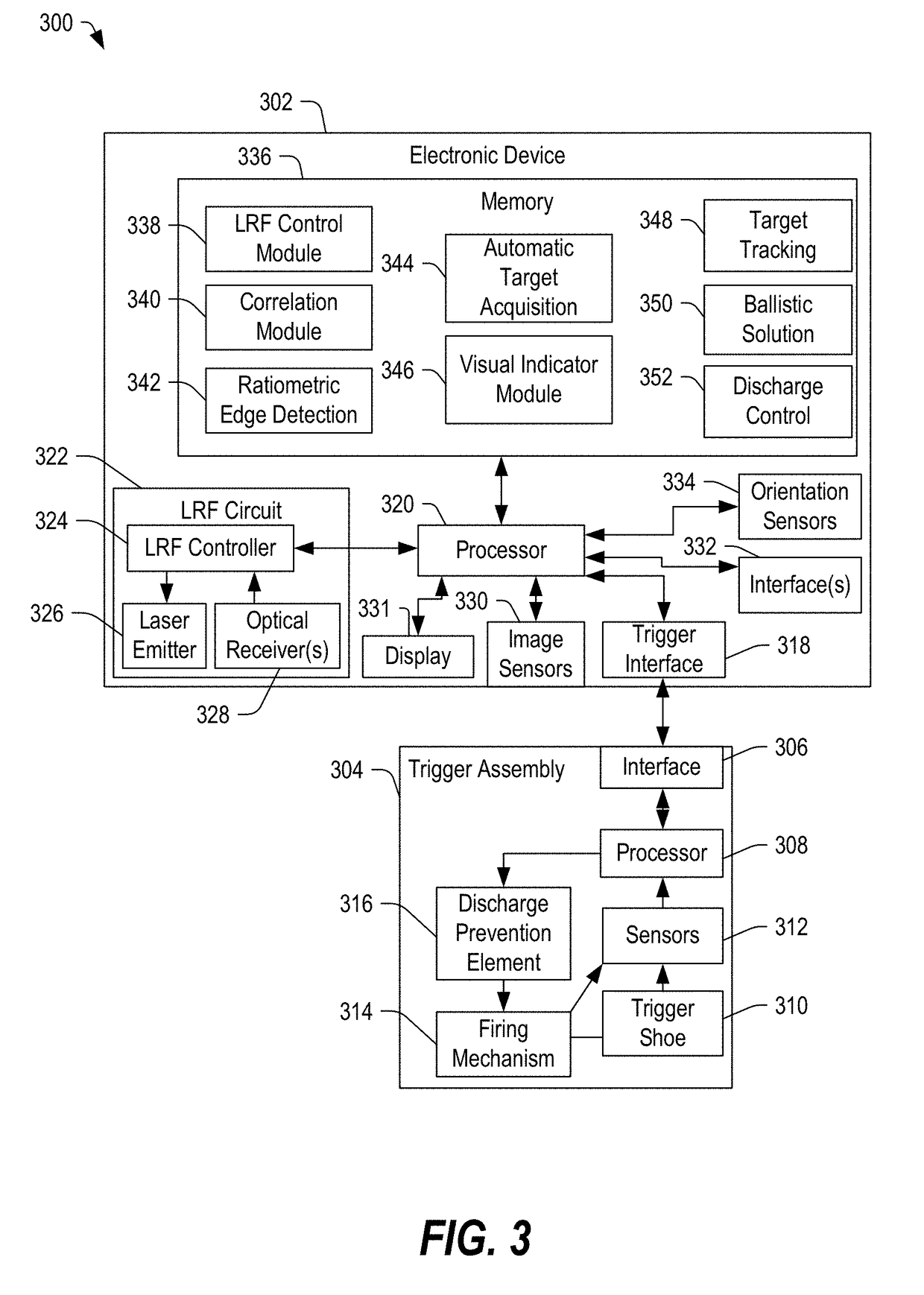
[0017]Embodiments of systems, devices, and method are described below that utilize measurements of intensity of reflections received by a laser rangefinder to detect a target within a view area. As the laser rangefinder sweeps across a view area, measurements of the intensity of the reflections received by the laser rangefinder may increase as the laser rangefinder sweeps onto an object and may decrease as the laser rangefinder sweeps off of the object. The changing measurements of the intensity be used to detect edges of a target based on the range data. In some embodiments, the device may be configured to automatically select the target based determination of the edges. In some embodiments, the device may include an optical scope, which may apply a visual marker to the selected target within a display of the scope. The visual marker may be positioned on the object within the view provided to the display, and a processor of the device may track the selected target within the view a...


PUM


Abstract

In some embodiments, a device may include a laser rangefinder circuit including an emitter configured to direct a focused beam toward a view area and including one or more optical sensors configured to receive light including ambient light and reflections associated with the view area. The device may further include a processor coupled to the laser rangefinder and configured to determine an edge of an object within the view area based on measurements of the reflections.

Description

FIELD[0001]The present disclosure is generally related to laser rangefinder systems, and more particularly to systems, devices, and methods of automatically detecting a target based on laser rangefinder data.BACKGROUND[0002]Laser rangefinder devices emit a focused beam toward a view area and detect light from the view area. A time difference between the emission of the focused beam and the reception of the reflected light can be used to determine a range between the laser rangefinder device and an object within the view area.[0003]In some instances, ambient light may be received by the optical sensor circuitry of the laser rangefinder circuit and may represent noise. Further, the emitted beam may diverge along a range or distance between the laser rangefinder device and the irradiated view area, such that the beam may partially overlap an object within the view area. Accordingly, the received optical data may include data corresponding to one or more objects within the view area.SUM...

Claims


Application Information

Patent Timeline
Patent Type & Authority Applications(United States)
IPC IPC(8): F41G3/06F41G1/35G01S17/08
CPCF41G3/065G01S17/08F41G1/35F41G1/473F41G3/08F41G3/165G01S17/10G01S7/487
Inventor LUPHER, JOHN HANCOCK
Owner TALON PRECISION OPTICS LLC
Why Eureka
Try Eureka