
Welding Glove

a glove and glove technology, applied in the field of glove welding, can solve the problems of affecting the user's middle, squeezing the trigger for such a long time, and can be quite painful for users

Inactive Publication Date: 2018-12-13
KIMBROUGH MARCUS
View PDF3 Cites 11 Cited by
  • Summary
  • Abstract
  • Description
  • Claims
  • Application Information

AI Technical Summary

Benefits of technology

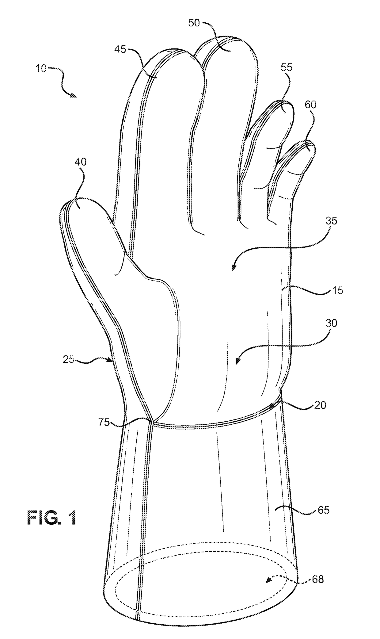
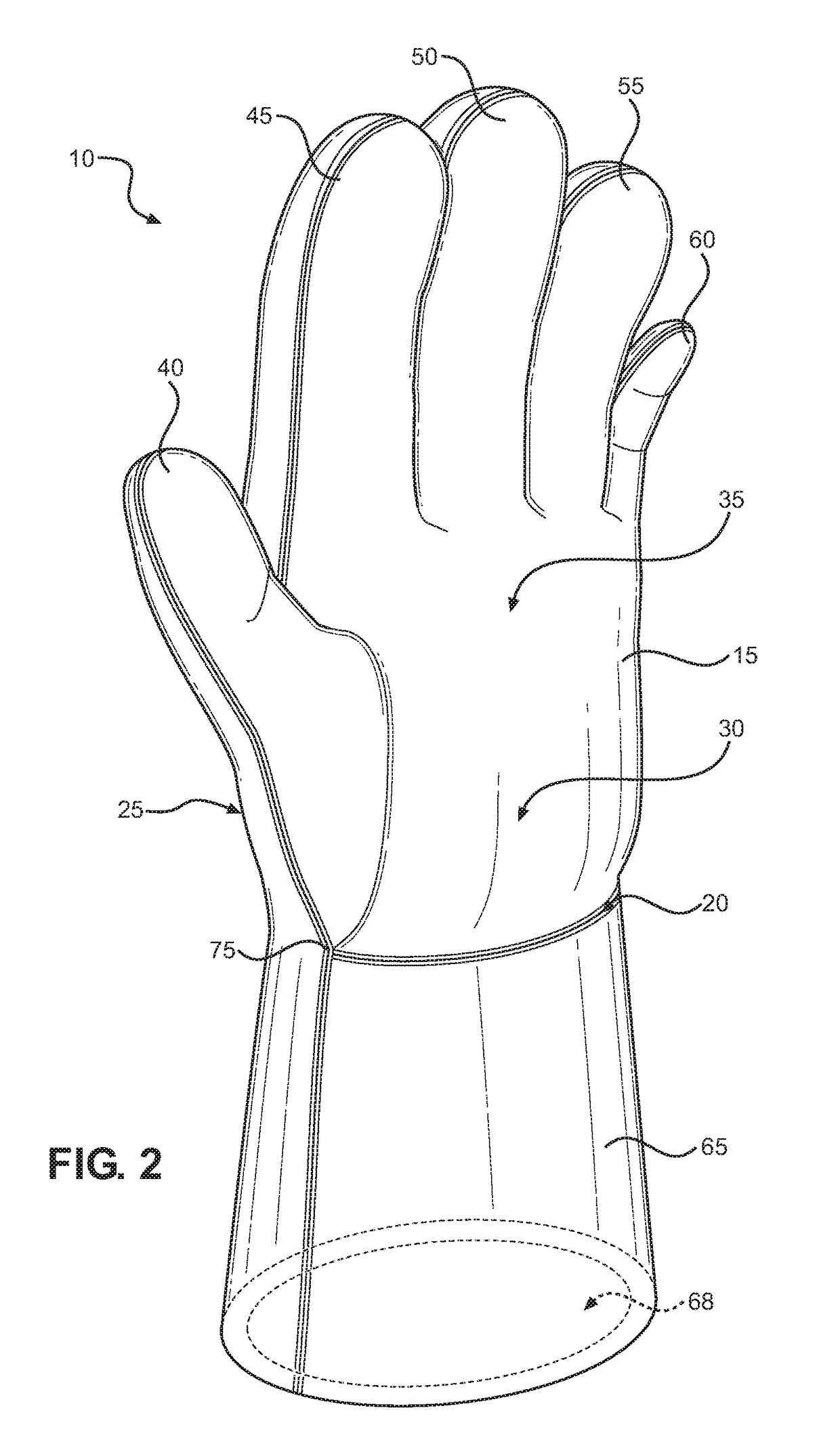
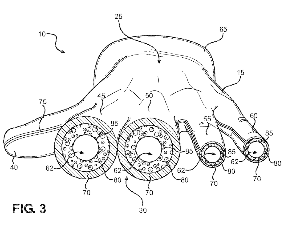
The present invention provides a welding glove that provides convenience for the user when operating a welding torch. The glove has a hand portion with a base, back side, palm side, and finger portions extending outwardly from the hand portion. It also includes an elongated cuff that extends over the user's wrist and forearm. The finger portions are sized to receive the user's fingers. The exterior layer is made of a flame retardant pliable material, while the intermediate layer is made of a flame retardant foam. The finger portions have different diameters, and the thumb and middle finger portions have a diameter that is double or triple the diameter of the ring finger and pinky finger portions. Overall, the welding glove provides comfort and safety for the user during welding operations.

Problems solved by technology

Squeezing the trigger for such extended amounts of time can be quite painful to a user, in particular to his or her middle and index fingers since, typically, those are the fingers squeezing the trigger and enduring the majority of the stress.
Currently, conventional welding gloves provide finger portions that include some padding but do not include index and middle finger portions that provide enough support configured to aid in squeezing a welding torch trigger and absorbing or alleviating the stress applied thereto.

Method used


Image

  • Welding Glove
  • Welding Glove
  • Welding Glove

Examples


Embodiment Construction

[0012]Reference is made herein to the attached drawings. Like reference numerals are used throughout the drawings to depict like or similar elements of the welding glove. The figures are intended for representative purposes only and should not be considered to be limiting in any respect.

[0013]Referring now to FIGS. 1-4, there are shown perspective views of the welding glove according to alternative embodiments of the present invention and a cross-sectional view of the index, middle, ring, and pinky finger portions of the welding glove, respectively. The welding glove 10 comprises a hand portion 15 including a base 20, a back side 25, a palm side 30, and a plurality of finger portions extending radially outwardly from a distal end 35 of the hand portion 15. The hand portion 15 includes an interior volume sized to receive a hand of a user therein. The plurality of finger portions include at least a thumb portion 40, an index finger portion 45, a middle finger portion 50, a ring finger...


PUM


Abstract

A welding glove is provided. The welding glove includes a plurality of finger portions including an index finger portion and middle finger portion having an exterior layer and intermediate layer that each include a diameter that is at least twice the diameter of the exterior layer and intermediate layer, respectively, of the thumb portion, the ring finger portion, and the pinky finger portion. In this way, when employing the welding glove, a user's trigger fingers include a larger cross-sectional area for actuating a welding trigger, which facilitates the absorption and redistribution of pressure on the user's fingers when actuating a welding trigger. In addition, the larger cross-sectional area aids in the absorption of any opposite force exerted onto a user's fingers by the welding trigger, thereby reducing the discomfort and stress associated with actuating a welding trigger for prolonged periods of time.

Description

BACKGROUND OF THE INVENTION[0001]The present invention relates to welding gloves. More specifically, the present invention relates to a welding glove including an index finger and middle finger portion that are at least twice the size of the remaining finger portions, for the purpose of facilitating the manipulation of a welding torch trigger and providing a means for alleviating the stress and discomfort associated with prolonged actuation of the welding torch trigger.[0002]Welders typically wear protective clothing, such as welding gloves, to protect against the heat generated by a welding torch and to protect against sputtering metal generated during the welding process. During the welding process, a welder must squeeze the trigger of a welding torch for prolonged periods of time. Squeezing the trigger for such extended amounts of time can be quite painful to a user, in particular to his or her middle and index fingers since, typically, those are the fingers squeezing the trigger...

Claims


Application Information

Patent Timeline
Patent Type & Authority Applications(United States)
IPC IPC(8): A41D19/015A41D13/08
CPCA41D13/08A41D19/01529
Inventor KIMBROUGH, MARCUS
Owner KIMBROUGH MARCUS
Learn More