
Disconnector Device And Arrangement For Disconnecting A Contactor

a technology of disconnector and contactor, which is applied in the direction of electrical switches, electrical apparatus, protective switch operating/release mechanisms, etc., can solve the problems of switch disconnector not having the robustness and reliability to handle millions of operations, contactor lacks means for providing a safe disconnection, and the switch disconnector is expensiv

Active Publication Date: 2018-12-13
ABB (SCHWEIZ) AG
View PDF0 Cites 0 Cited by
  • Summary
  • Abstract
  • Description
  • Claims
  • Application Information

AI Technical Summary

Benefits of technology

The disconnector device described in this patent has several advantages. It provides a contactor with an additional feature that allows it to act as a reliable switch and safely disconnect. Compared to other disconnection devices, it is more cost-efficient. Additionally, it enables a smaller arrangement of contactor and disconnector. The device can be used as an accessory or a built-in feature in the contactor. The patent also describes a variation where the first shaft operates both means in a single movement, making it easier to use.

Problems solved by technology

However the contactor lacks means for providing a safe disconnection when being in open position, i.e. in a position disconnecting the electrical power circuit.
Such safe disconnection is a requirement for ensuring that the contacts of the contactor will not close by mistake or by some malfunctioning, as this would be life threatening e.g. for a person servicing the electrical power circuit or device that is being switched by the contactor.
The switch disconnector normally lacks the robustness and reliability for handling millions of operations.
The switch disconnectors are however expensive and may be difficult to operate.
If the switch disconnector is provided with means for remote operation, e.g. in the form of a motor drive, the arrangement of contactor and switch disconnector is rendered complicated as well as expensive.

Method used


Image

  • Disconnector Device And Arrangement For Disconnecting A Contactor
  • Disconnector Device And Arrangement For Disconnecting A Contactor
  • Disconnector Device And Arrangement For Disconnecting A Contactor

Examples


Embodiment Construction

[0025]In the following description, for purposes of explanation and not limitation, specific details are set forth such as particular architectures, interfaces, techniques, etc. in order to provide a thorough understanding. In other instances, detailed descriptions of well-known devices, circuits, and methods are omitted so as not to obscure the description with unnecessary detail. Same reference numerals refer to same or similar elements throughout the description.

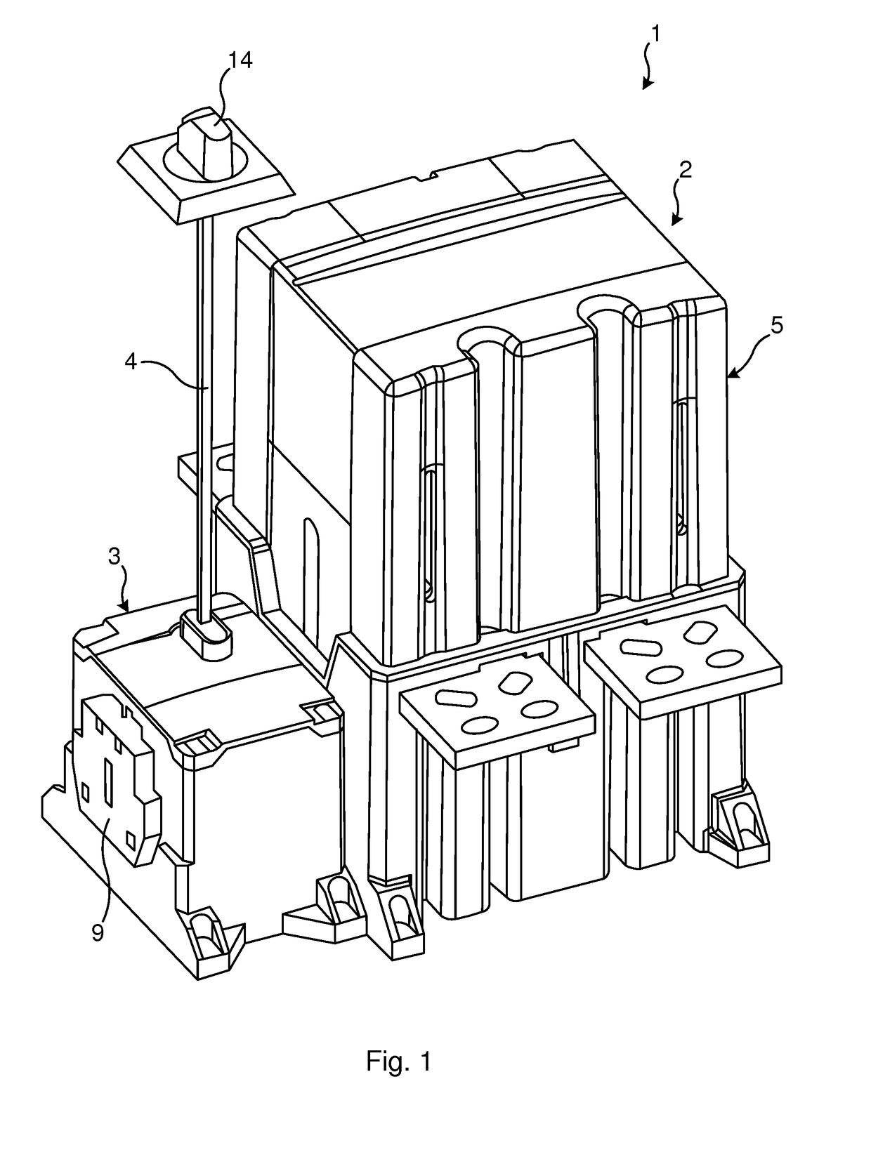
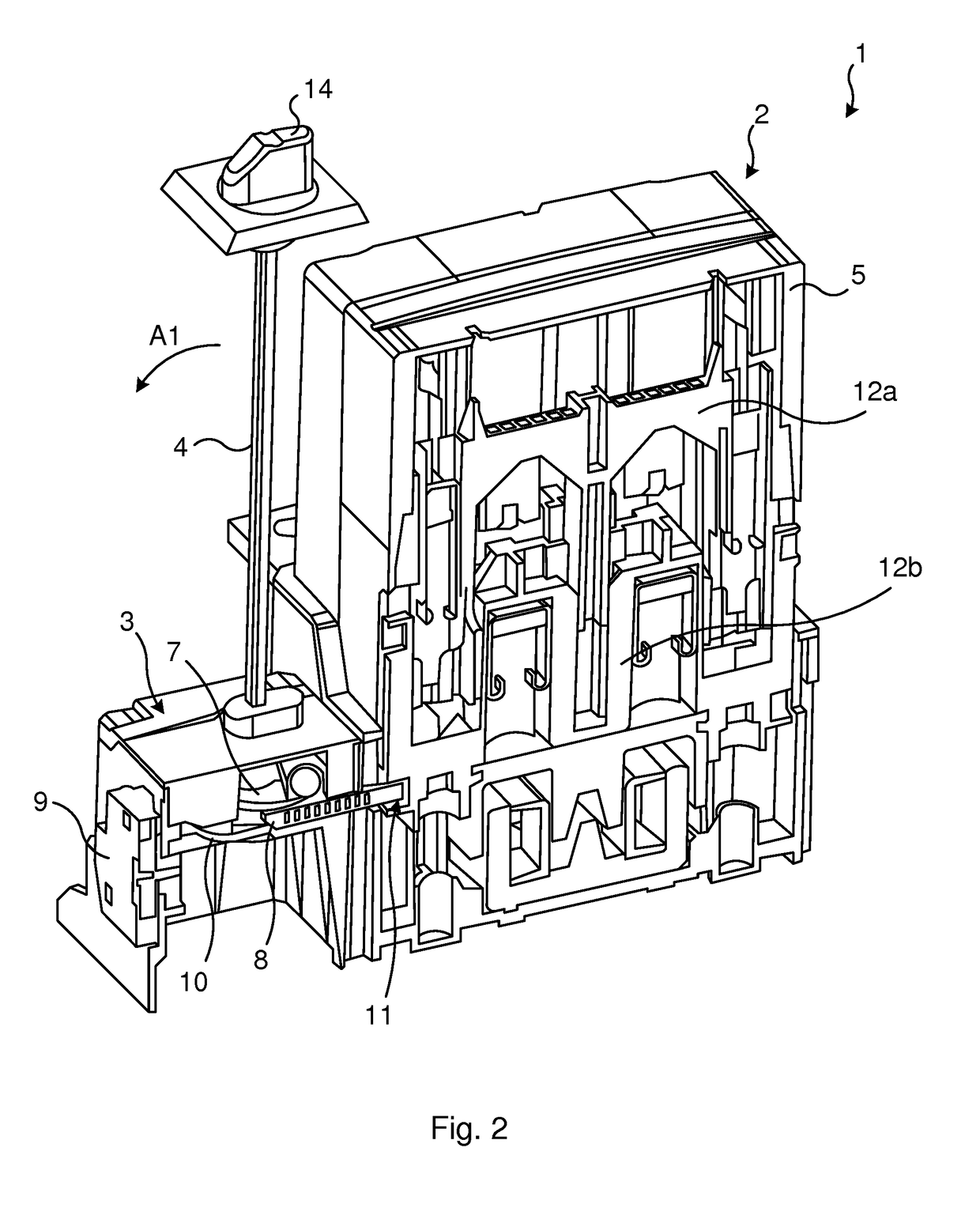
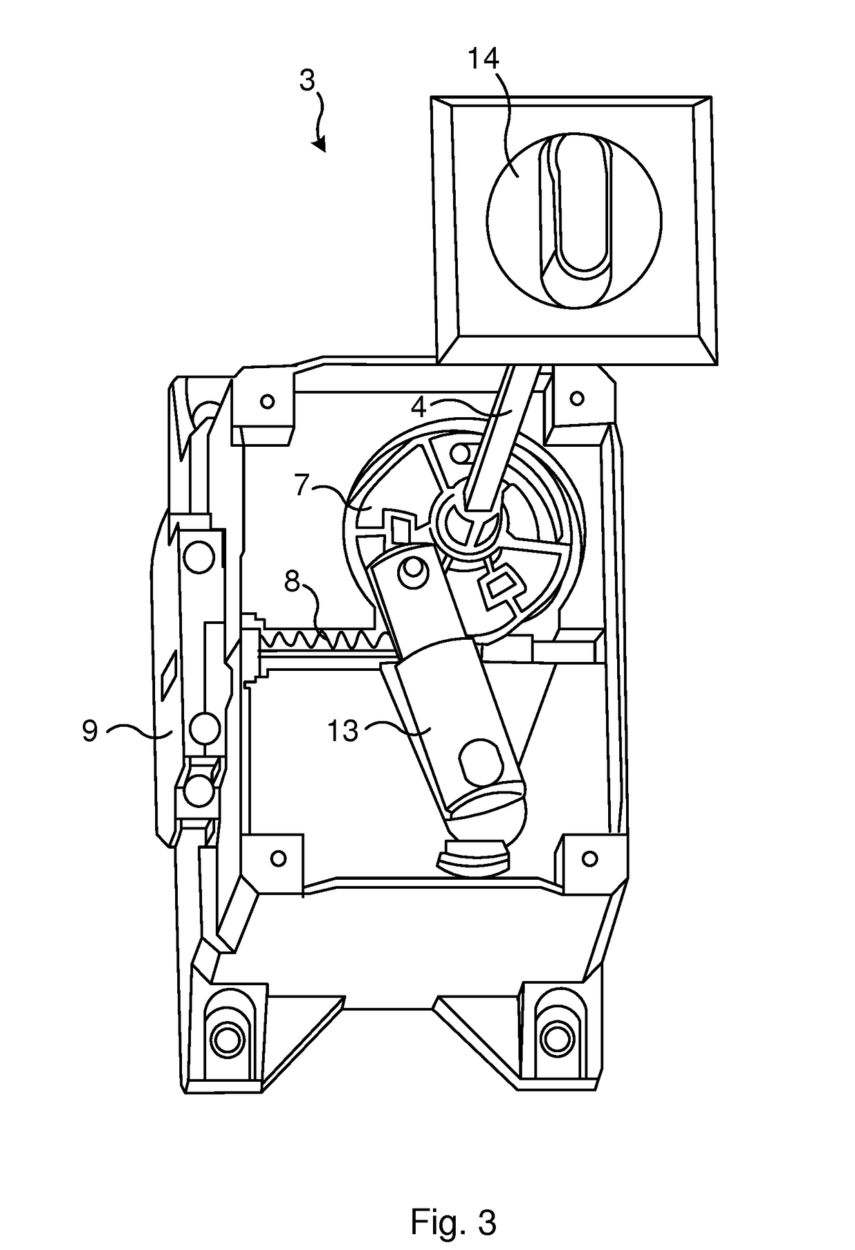
[0026]FIG. 1 illustrates an arrangement for safe disconnection of an electrical circuit according to the present invention. The arrangement 1 comprises a contactor device 2, in the following also denoted contactor 2, and a disconnector device 3, in the following also denoted disconnector 3. The disconnector 3 may, as illustrated in FIG. 1, be mounted on the side of the contactor 2, i.e. mounted to the housing 5 thereof. Electrical wiring may be provided between the control circuit (not illustrated in FIG. 1) of the contac...


PUM


Abstract

A disconnector device is provided for disconnecting an electrical circuit, wherein the electrical circuit is switched by a contactor between an open position and a closed position, the disconnector device using the contactor for disconnecting the electric circuit. The disconnector device locks the contactor in the open position, in which open position contacts of the contactor are in a first position disconnecting the electrical circuit. An arrangement including the disconnector device and a contactor is also provided.

Description

TECHNICAL FIELD[0001]The technology disclosed herein relates generally to the field of contactors and disconnectors used in electrical networks, and in particular to a disconnector device and arrangement comprising a contactor and the disconnector device for disconnecting an electric circuit.BACKGROUND[0002]A contactor is an electrically controlled switch used for switching an electrical circuit or electrical device with high current ratings. The contactor is controlled by control circuitry having a much lower power level than the electric circuit or device that is being switched by the contactor. The contactor comprises contacts, i.e. the current carrying part of the contactor, and a mechanism (for instance an electromagnet or coil) for closing and opening these contacts. The contactor is normally a mono-stable remotely operated device, operated e.g. by the mentioned control circuitry. The contactor is built for handling millions of operations and is a very reliable and robust devi...

Claims


Application Information

Patent Timeline
Patent Type & Authority Applications(United States)
IPC IPC(8): H01H9/22H01H71/10H01H71/56H01H9/28
CPCH01H9/22H01H71/1054H01H71/56H01H9/281
Inventor JOHANSSON, GUNNARANGELL, MARKUSNILSSON, ALFREDJOHANSSON, LINNEA
Owner ABB (SCHWEIZ) AG
Learn More