
Bus bar for solar cell component

a solar cell and component technology, applied in the field of bus bars, can solve the problems of high cost, complex manufacturing process, large size of electric components used thereby, etc., and achieve the effect of reducing the cost of the manufacturing process, simple terminal box structure, and good heat dissipation property

Inactive Publication Date: 2017-05-11
OVIS ENTERPRISES
View PDF3 Cites 0 Cited by
  • Summary
  • Abstract
  • Description
  • Claims
  • Application Information

AI Technical Summary

Benefits of technology

The patent text describes a bus bar for a solar cell component that has good heat dissipation properties and a simple terminal box structure. This bus bar has the technical effect of reducing the cost of manufacturing the solar cell component. The advantage of using only one bus bar in a single solar cell component is that it significantly reduces the area for assembly. The terminal box used with the bus bar is only acted as a protective casing, and there is no need to install electrical components such as diodes. The bus bar provided by the invention can close attach to the glass skin layer of the solar cell component and provide excellent heat dissipation efficiency. Additionally, the manufacturing process of the bus bar is simple, and the cost of the process is reduced. The bus bar can be directly connected to external electrical wires in series and has the technical effect of easy to assemble and easy to maintain.

Problems solved by technology

However, the existing bus bars have the following problems:1. Conventional bus bars employ at least two rows of bus bars to operate normally and hence, a large area on the component is needed.2. The terminal box used with the existing bus bars has other electrical components such as diodes, printed circuit boards (PCB) or other wires installed therein and hence, the complexity of the arrangement inside the terminal box is very high.
The terminal box needs to pass various safety tests before being used and the manufacturing process is complicated and high-cost.3. Solar cell components are components that utilize large electrical current and extremely high power and hence, the sizes of electric components used thereby are large and have high heating power.
Therefore, there is a problem of overheat, and the efficiency or lifetime of the solar cell components is reduced.4. The manufacturing process and assembling process of the existing bus bars are complicated.

Method used


Image

  • Bus bar for solar cell component
  • Bus bar for solar cell component
  • Bus bar for solar cell component

Examples


Embodiment Construction

[0027]Reference will now be made in detail to the exemplary embodiments of the instant disclosure, examples of which are illustrated in the accompanying drawings. Wherever possible, the same reference numbers are used in the drawings and the description to refer to the same or like parts.

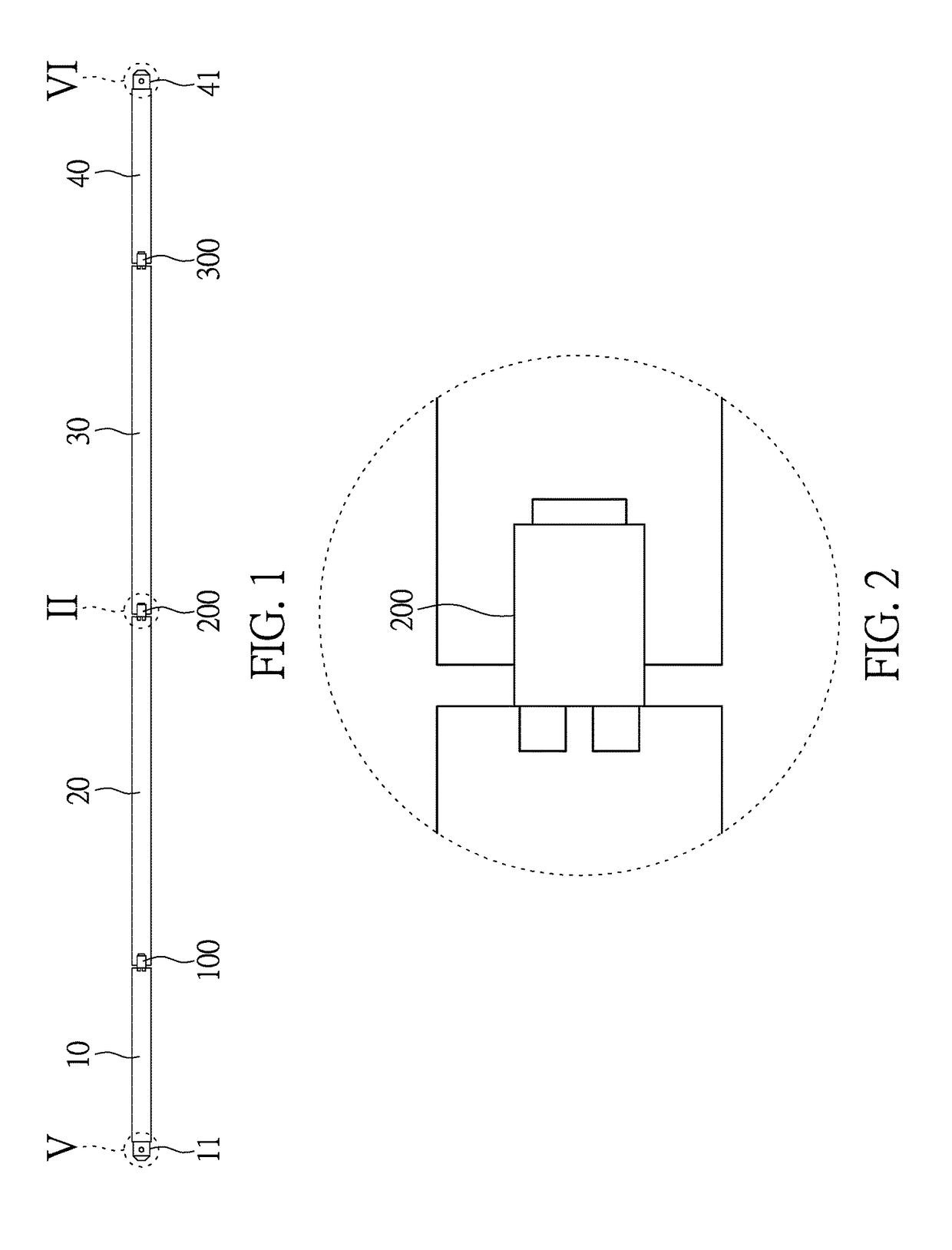
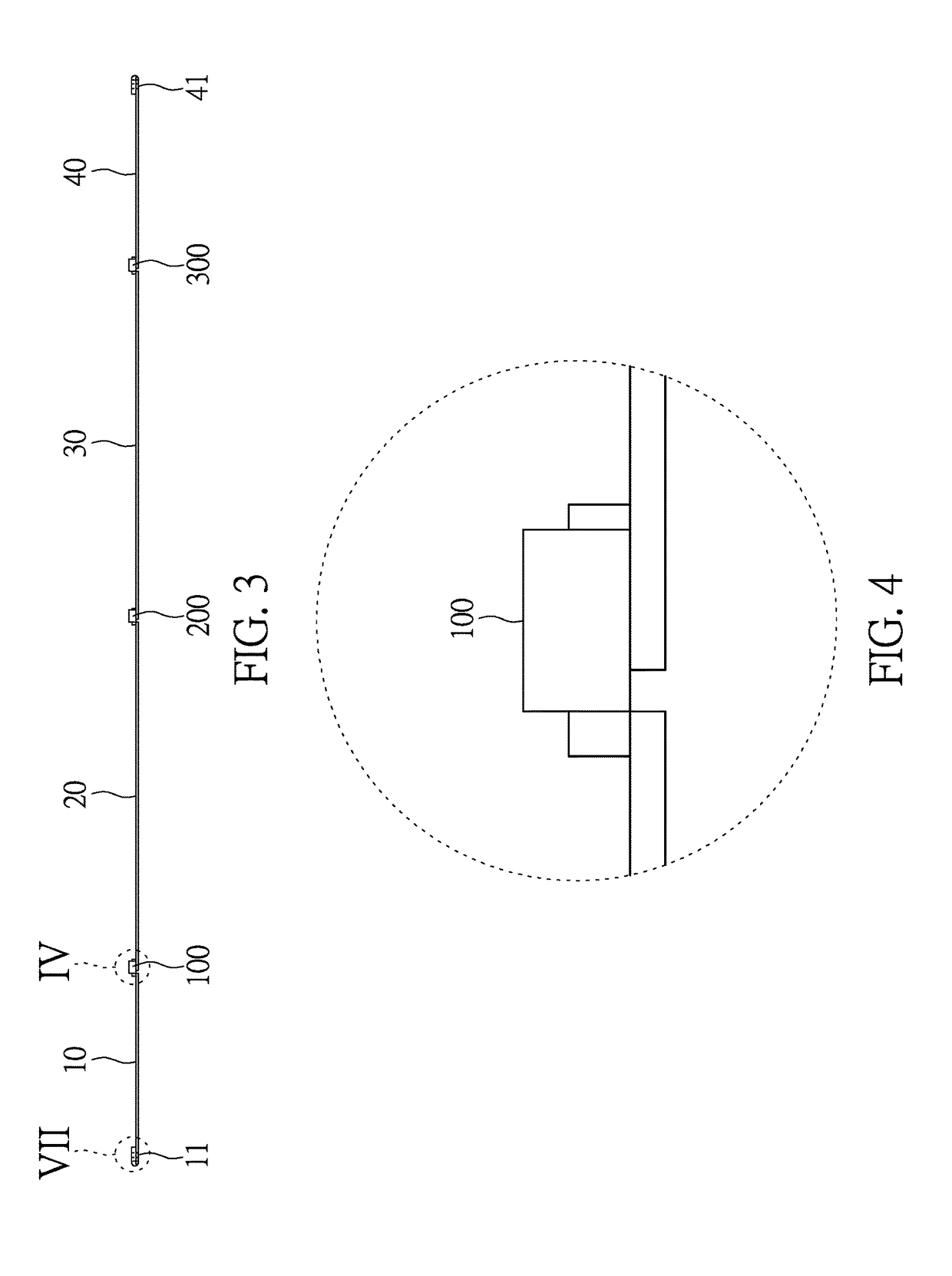
[0028]Please refer to FIG. 1 to FIG. 4. FIG. 1 to FIG. 4 shows the preferable embodiment of the bus bar for solar cell component provided by the instant disclosure. The bus bar for solar cell component comprises a first copper ribbon 10, a second copper ribbon 20, a third copper ribbon 30 and a fourth copper ribbon 40. The copper ribbons connect sequentially and end-to-end. A first diode 100 electrically bridges the first copper ribbon 10 and the second copper ribbon 20, a second diode 200 electrically bridges the second cooper ribbon 20 and the third copper ribbon 30, and a third diode 300 electrically bridges the third copper ribbon 30 and the fourth copper ribbon 40. A first electrical energy out...


PUM

PropertyMeasurementUnit
electrical energyaaaaaaaaaa
lengthaaaaaaaaaa
electricalaaaaaaaaaa

Abstract

A bus bar for solar cell component is provided. The bus bar includes a first copper ribbon, a second copper ribbon, a third copper ribbon and a fourth copper ribbon connected end-to-end. A first diode electrically bridges the first and the second copper ribbon; a second diode electrically bridges the second and the third copper ribbon; and a third diode electrically bridges the third and the fourth copper ribbon. A first electrical energy output terminal is formed at an end of the first copper ribbon corresponding to the second copper ribbon, and a second electrical energy output terminal is formed at an end of the fourth copper ribbon corresponding to the third copper ribbon.

Description

BACKGROUND[0001]1. Technical Field[0002]The instant disclosure relates to a bus bar, in particular, to a bus bar for solar cell components.[0003]2. Description of Related Art[0004]The bus bars in the solar cell component are used to connect a plurality of solar cells, and to connect the solar cell component to external components through a terminal box, thereby achieving the object of convergence. However, the existing bus bars have the following problems:[0005]1. Conventional bus bars employ at least two rows of bus bars to operate normally and hence, a large area on the component is needed.[0006]2. The terminal box used with the existing bus bars has other electrical components such as diodes, printed circuit boards (PCB) or other wires installed therein and hence, the complexity of the arrangement inside the terminal box is very high. The terminal box needs to pass various safety tests before being used and the manufacturing process is complicated and high-cost.[0007]3. Solar cel...

Claims


Application Information

Patent Timeline
Patent Type & Authority Applications(United States)
IPC IPC(8): H01L31/02H01L31/05
CPCH01L31/0512H01L31/0201H01L31/0508H01L31/044Y02E10/50
Inventor LIN, CHING-YU
Owner OVIS ENTERPRISES
Learn More