
Motion model synthesizer methods and systems

a technology of motion model and synthesizer, applied in the direction of electric digital data processing, program-controlled manipulators, instruments, etc., can solve the problems of low probability of being physically correct, complex motion of articulated assemblies, and complex symmetry

Inactive Publication Date: 2018-12-20
KELLY MICHAEL
View PDF0 Cites 5 Cited by
  • Summary
  • Abstract
  • Description
  • Claims
  • Application Information

AI Technical Summary

Benefits of technology

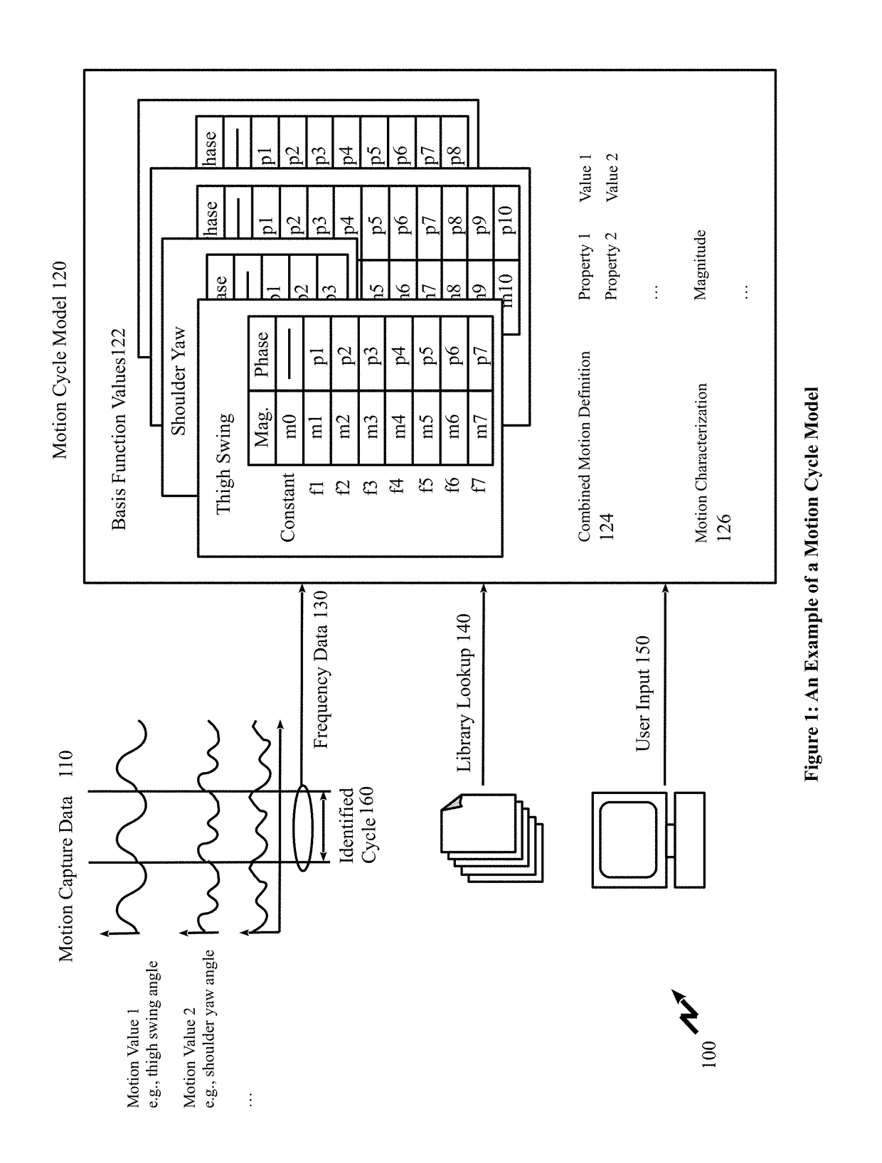
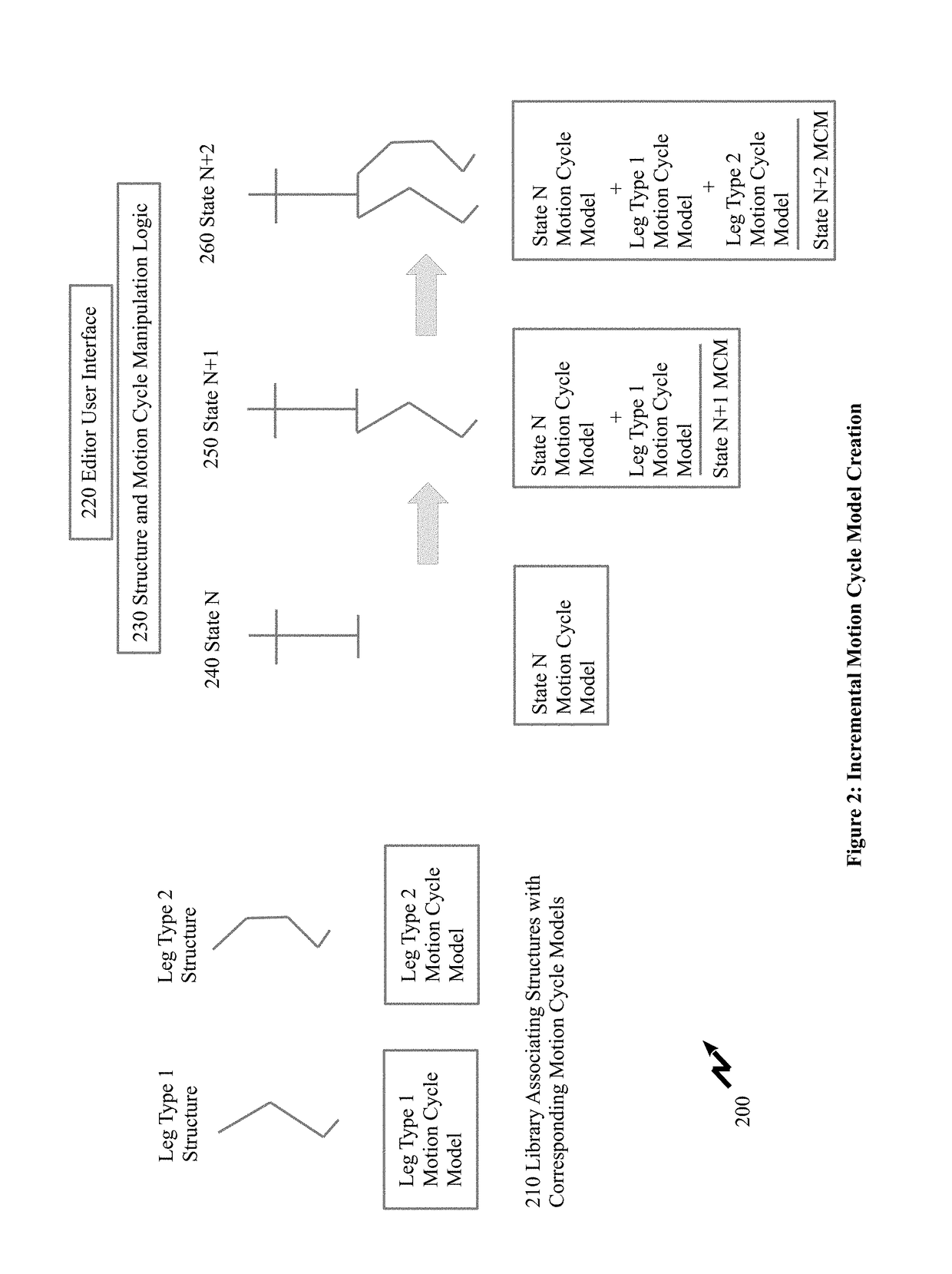
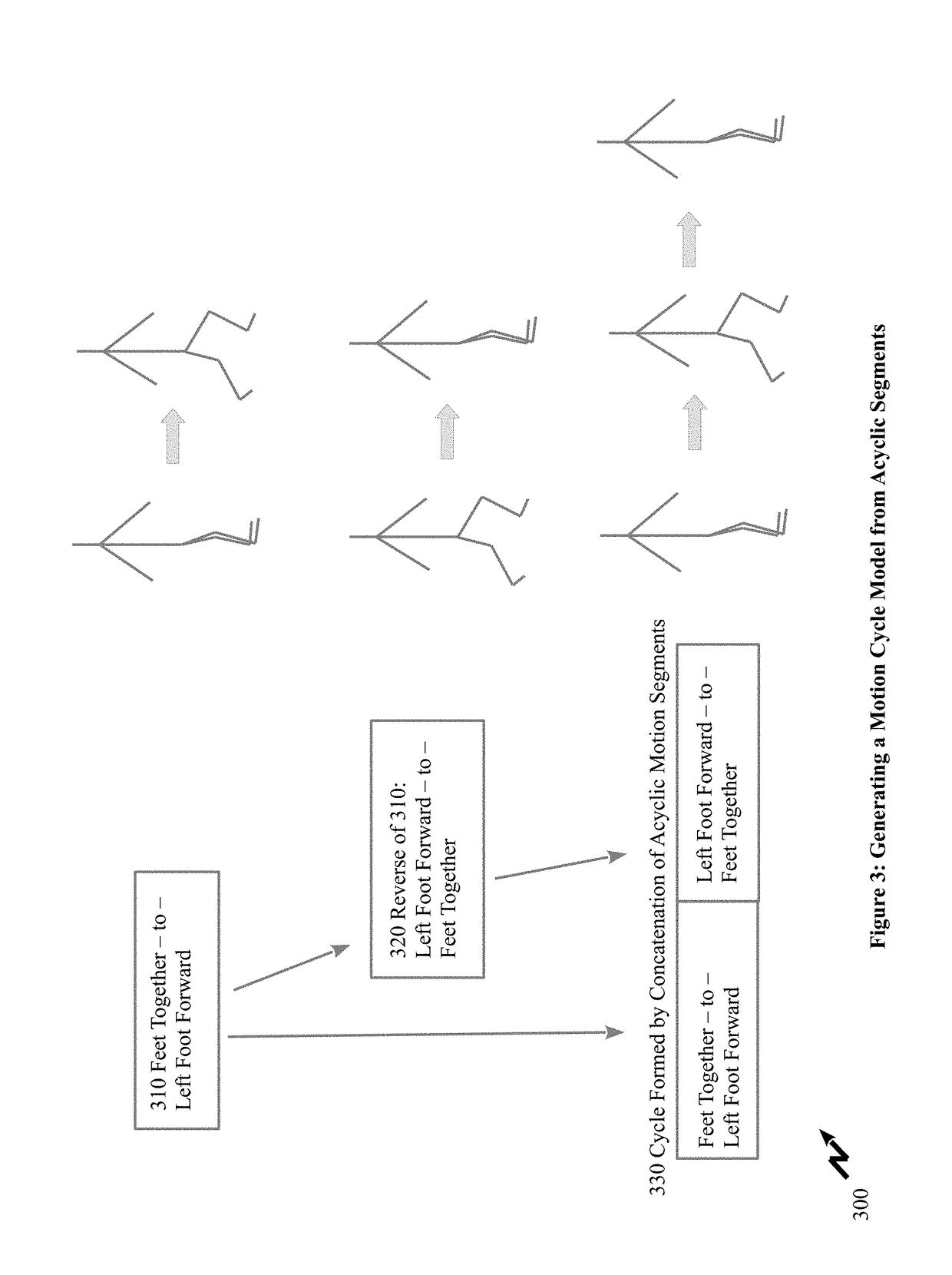
The present invention aims to improve the creation, analysis, and modification of motion specifications of articulated assemblies such as robots, prostheses, and animated characters. It provides a method for creating a motion cycle model by incrementally defining the motion of an articulated assembly and viewing and modifying the elements and properties of the motion cycle model. It also allows for the creation of a multimodel, a motion model comprised of a set of motion cycle models plus branching information, and the import and export of actuation cycle and multimodel specifications in whole or in combination with other systems. Overall, the invention provides a more efficient and effective way to create and modify motion specifications for articulated assemblies.

Problems solved by technology

The motion of an articulated assembly can be complex even for a simple assembly because the number of possible states is, at worst, the product of all of the possible states of the individual elements, and because a motion specification also includes an indication of a desired sequence of those states.
In the domain of motion specification, symmetry is more complex because it may include a time- or phase-based component, and because the assembly elements associated with the symmetry may themselves not be symmetric.
Although the motion may be smooth, it has a very low probability of being physically correct because not physical properties aside from positional information are used in blending.
Furthermore, the blending operation itself requires substantial computational resources, unlike the linear playback of either gait involved individually.

Method used


Image

  • Motion model synthesizer methods and systems
  • Motion model synthesizer methods and systems
  • Motion model synthesizer methods and systems

Examples


Embodiment Construction

[0077]This invention relates to the design and simulation of articulated assemblies, such as robots or animated characters, and more specifically to the model used to represent motions of such assemblies, and to the structures, systems and methods used to construct, view, analyze, and modify such a model.

[0078]The ensuing description provides representative embodiment(s) only, and is not intended to limit the scope, applicability or configuration of the disclosure. Rather, the ensuing description of the embodiment(s) will provide those skilled in the art with an enabling description for implementing an embodiment or embodiments of the invention. It being understood that various changes can be made in the function and arrangement of elements without departing from the spirit and scope as set forth in the appended claims. Accordingly, an embodiment is an example or implementation of the inventions and not the sole implementation. Various appearances of “one embodiment,”“an embodiment”...


PUM


Abstract

Articulated assemblies are all around us in nature as well as within the artificial environments and artificial systems we create. Computer based simulations are used to view, analyze, and modify motion specifications and sequences for articulated assemblies in the generation of avatars for multimedia and designing robotic / android systems. Articulated assembly specifications along with terrain and physical laws are employed in establishing an actuation and motion sequence for the assembly. However, other factors such as emotion, state of mind, etc. impact how the assembly actually moves and the physical aspect of the assembly. Embodiments of the invention allow for management of cyclic and acyclic elements to the overall motion through graphical user interfaces as well as the rapid establishment of new motion models through fractional combination of existing motion models as well as the association of a motion model to multiple articulated assemblies allowing simulations of herds, crowds etc.

Description

[0001]This patent application claims the benefit of priority from U.S. Provisional Patent Application 62 / 522,389 filed Jun. 20, 2017 entitled “Motion Model Synthesizer”, the entire contents of which are herein incorporated by reference.FIELD OF THE INVENTION[0002]This invention relates to the design and simulation of articulated assemblies, such as robots or animated characters, and more specifically to the model used to represent motions of such assemblies, and to systems and methods for viewing, analysing, and modifying of such models.BACKGROUND OF THE INVENTION[0003]Articulated assemblies are comprised of rigid or flexible segments of arbitrary shape, and the joints between them. Segments may additionally have mechanisms attached to them which will affect the way the segment will interact with an obstruction, a support surface, or other segments. For example, a segment may have a wheel or track mechanism at one end to provide control of the endpoint when it is in contact with a s...

Claims


Application Information

Patent Timeline
Patent Type & Authority Applications(United States)
IPC IPC(8): B25J9/16B25J19/00G06F17/50
CPCB25J9/1605B25J19/007G06F17/5009G06F30/17G06F30/20B25J9/1602B25J9/16G06F2119/14
Inventor KELLY, MICHAEL
Owner KELLY MICHAEL
Learn More