Plastic film applicator with a braking function

a technology of plastic film and applicator, which is applied in the direction of transportation and packaging, thin material processing, and article delivery, etc., can solve the problems of insufficient tension of plastic film extended and affect the wrapping, and achieve the effect of enhancing application convenien

Inactive Publication Date: 2018-12-20
HUANG YU CHUN
View PDF4 Cites 4 Cited by
  • Summary
  • Abstract
  • Description
  • Claims
  • Application Information

AI Technical Summary

Benefits of technology

[0003]The present invention has been accomplished under the circumstances in view. It is the main object of the present invention to provide a plastic film applicator for the application of a plastic film roll, which provides a braking function to enhance application convenience.
[0004]To achieve this and other objects of the present invention, a plastic film applicator comprises an applicator body and a brake device. The applicator body comprises a mandrel, and a grip connected to one end of the mandrel. The brake device comprises a bearing ring and an elastic braking pad. The bearing ring is detachably mounted between the mandrel and grip of the applicator body for enabling the elastic braking pad to be biased toward the applicator body by an external force.
[0005]Thus, after the user attached a plastic film roll onto the mandrel of the applicator body into abutment at the bearing ring of the brake device, the user can hold the grip of the applicator body for allowing the plastic film roll to be rotated relative to the applicator body so that the plastic film of the plastic film roll can be extended out for wrapping. During wrapping, the user can press the thumb on the elastic braking pad to timely force the elastic braking pad toward the plastic film roll, forcing the abutment protrusion of the elastic braking pad into abutment against the film roll shaft, and thus, a braking effect is provided to the film roll shaft to stretch the extended plastic film for wrapping.

Problems solved by technology

But for the user, due to standing posture, it is inconvenient to brake the plastic film roll directly with the hand in the actual operation, and the tension of the extended plastic film can be insufficient, affecting the wrapping.

Method used


Image

  • Plastic film applicator with a braking function
  • Plastic film applicator with a braking function
  • Plastic film applicator with a braking function

Examples


Embodiment Construction

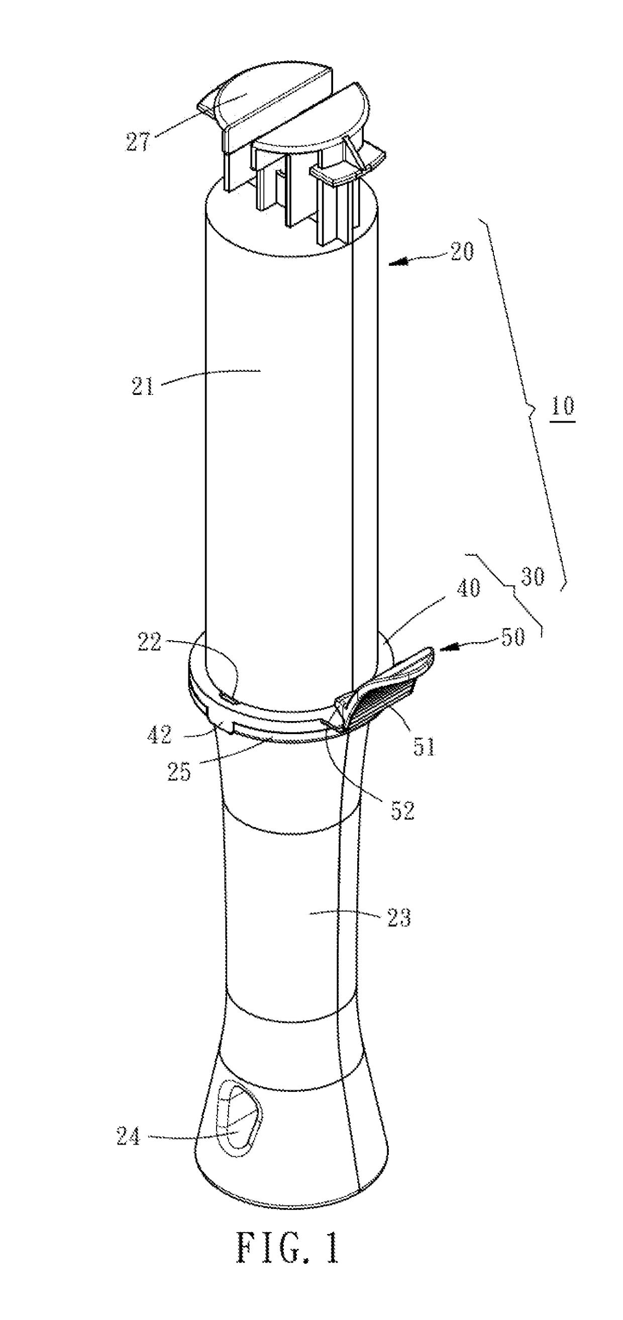
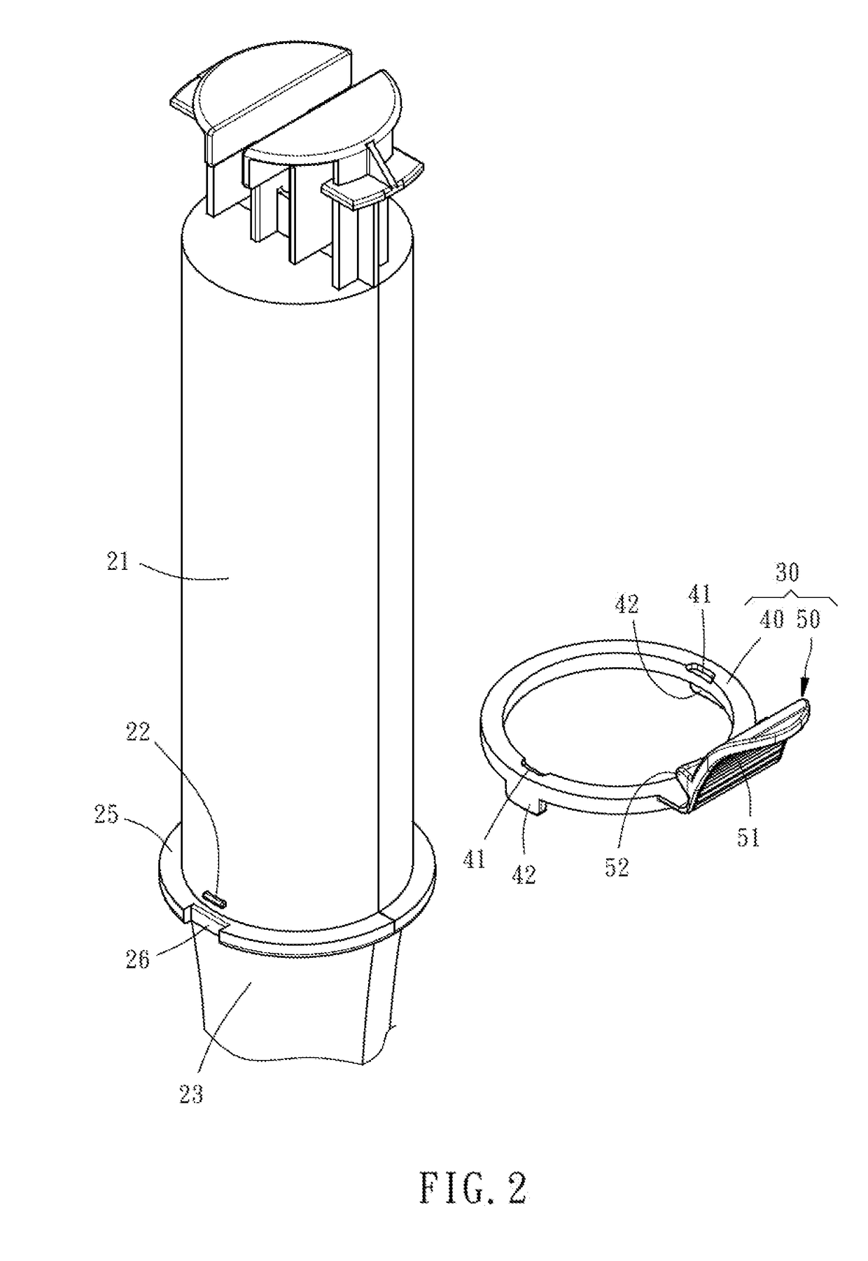
[0018]Referring to FIGS. 1 and 4, a plastic film applicator 10 in accordance with the present invention is shown. The plastic film applicator 10 is configured for the application of a plastic film roll 12. As illustrated, the plastic film roll 12 comprises a film roll shaft 14, and a roll of plastic film 16 wound round the film roll shaft 14. As illustrated in FIGS. 1 and 2, the plastic film applicator 10 comprises an applicator body 20 and a brake device 30.

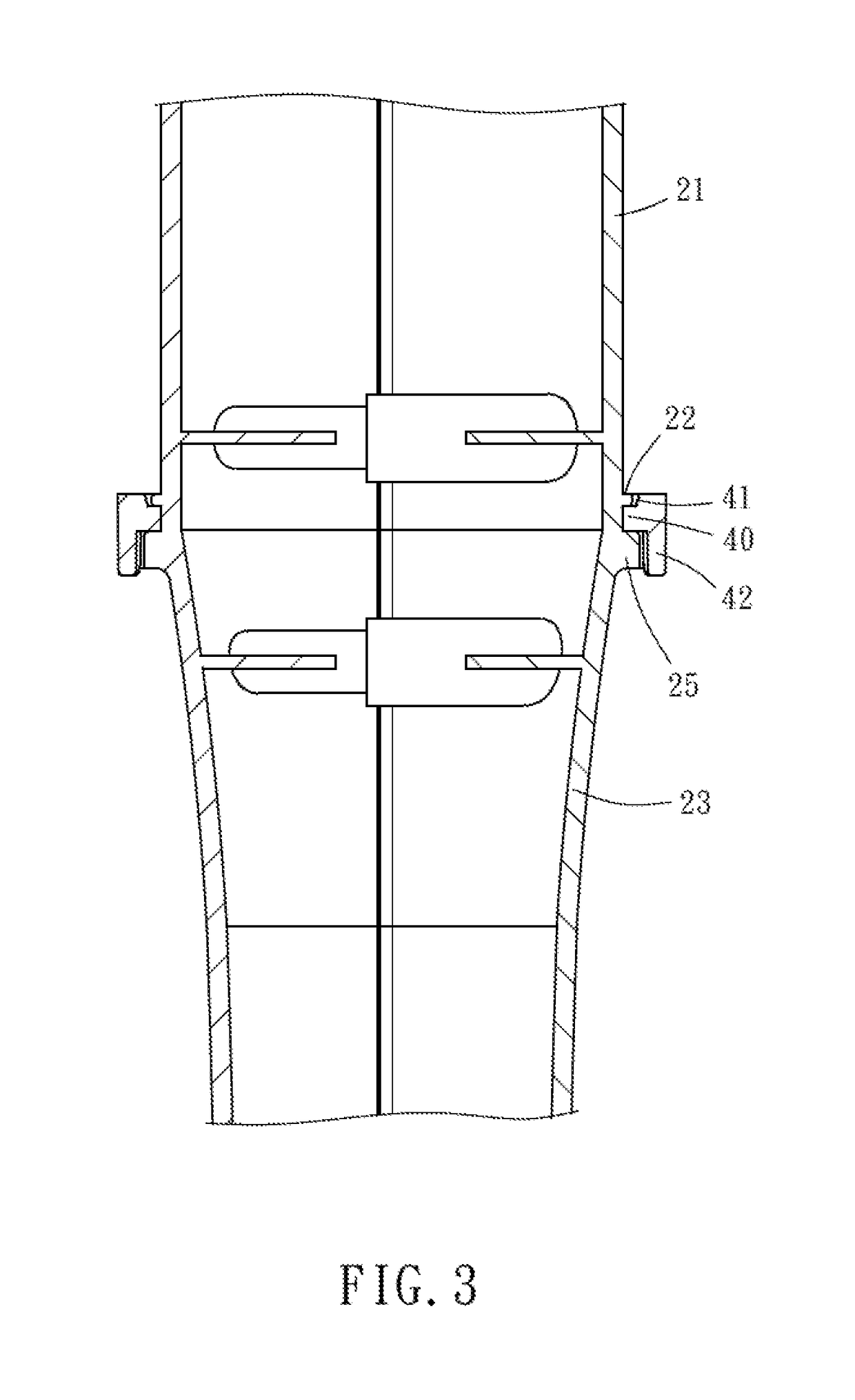
[0019]The applicator body 20 is made of an elastic material (such as, plastics), comprising a mandrel 21, a grip 23 coaxially connected to one end of the mandrel 21, and a flange 25 extended around the periphery of the junction between the mandrel 21 and the grip 23.

[0020]The mandrel 21 has two stopping protrusions 22 located on the outer periphery thereof at two opposite sides. The grip 23 has a hanging hole 24 located at one end thereof remote from the mandrel 21. The flange 25 defines two opposing positioning recesses 26 resp...


PUM

PropertyMeasurementUnit
external forceaaaaaaaaaa
areaaaaaaaaaaa
tensionaaaaaaaaaa

Abstract

A plastic film applicator includes an applicator body including a mandrel and a grip connected to the mandrel, and a brake device including a bearing ring detachably mounted between the mandrel and grip of the applicator body for enabling the elastic braking pad to be biased toward the applicator body by an external force and an elastic braking pad having one end thereof connected to the bearing ring and elastically biasable by an external force. After the user attached a plastic film roll onto the mandrel of the applicator body, the user can press the thumb on the elastic braking pad to timely force the elastic braking pad toward the plastic film roll, forcing the abutment protrusion of the elastic braking pad into abutment against the film roll shaft, and thus, a braking effect is provided to the film roll shaft to stretch the extended plastic film for wrapping.

Description

BACKGROUND OF THE INVENTION1. Field of the Invention[0001]The present invention relates to plastic film application technology, and more particularly to a plastic film applicator with a braking function.2. Description of the Related Art[0002]When using a plastic film roll for wrapping goods, the plastic film must be stretched to produce a certain tension so that the plastic film can be positively wrapped about the goods. According to conventional techniques, the user needs to give a certain contact force to the plastic film of the plastic film roll to provide a certain brake effect, keeping the extended plastic film in a stretched status for wrapping. But for the user, due to standing posture, it is inconvenient to brake the plastic film roll directly with the hand in the actual operation, and the tension of the extended plastic film can be insufficient, affecting the wrapping.SUMMARY OF THE INVENTION[0003]The present invention has been accomplished under the circumstances in view. ...

Claims


Application Information

Patent Timeline
Patent Type & Authority Applications(United States)
IPC IPC(8): B65H37/00
CPCB65H37/005B65H2701/1752B65H2701/1944B65H2403/725B65H2407/21
Inventor HUANG, YU-CHUN
Owner HUANG YU CHUN
Why Eureka
Try Eureka