Check patentability & draft patents in minutes with Patsnap Eureka AI!

Foreign material exclusion device and retaining member therefor

Active Publication Date: 2018-12-20
ADVANCED F M E PROD
View PDF4 Cites 3 Cited by
  • Summary
  • Abstract
  • Description
  • Claims
  • Application Information

AI Technical Summary

Benefits of technology

The present invention provides an alternative design for a foreign material exclusion device that is reliable, durable, easy to maintain, and can be assembled and disassembled in the field as necessary. The device has a unique retaining member including a post and a cap, the post having a base adapted to provide support for a resilient body and facilitate removal of the device from an area of a construction. The retaining member can have one or more posts connected to a common base, and a cap with a rim that forms an upper plate is fitted over into the post, being compressed against the body of the foreign material exclusion device. The arrangement of through bores in the post and cap provides additional torsional, axial, and radial rigidity to the body and sealing the retaining member. The indicia printed directly onto a visible surface of the cap or base provides easily accessible information regarding the retaining member and its intended use.

Problems solved by technology

If not prevented, retrieved or noticed, such parts can have the potential to destroy or at least damage a particular unit and produce varying consequences, potentially catastrophic.
Prevention of debris contacting rotating turbine blades during operation is critically important as damaged blades impart vibration requiring controlled shutdown or explosive breakage of the blade causing extensive damage and uncontrolled shutdown.

Method used


Image

  • Foreign material exclusion device and retaining member therefor
  • Foreign material exclusion device and retaining member therefor
  • Foreign material exclusion device and retaining member therefor

Examples


second embodiment

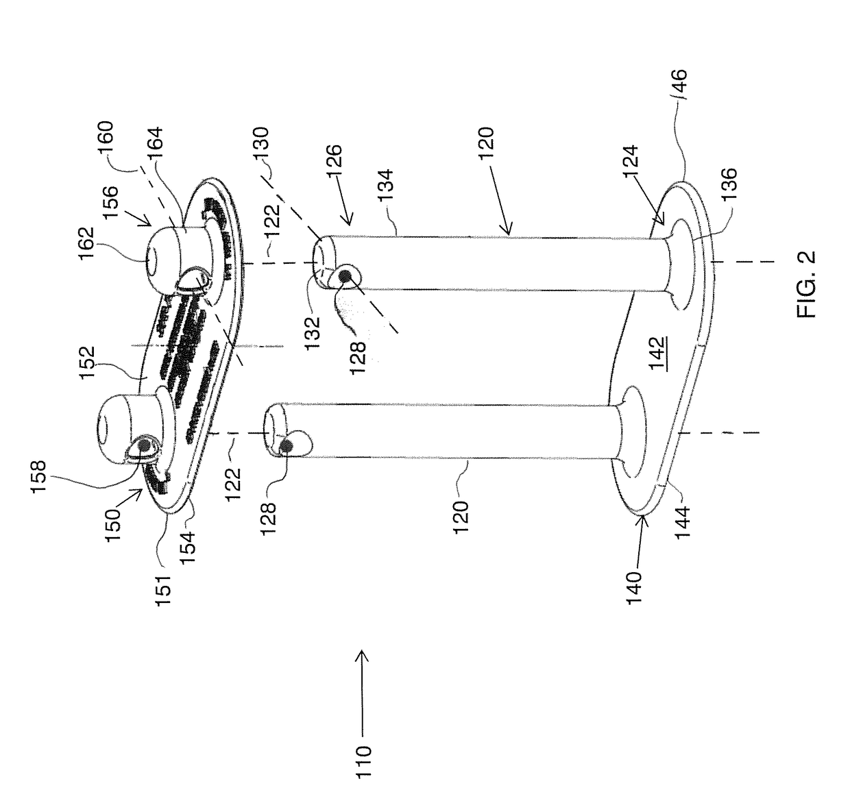
[0039]FIG. 2 illustrates a retaining member 110 including a pair of posts 120, a base 140 and a cap 150. Base 140 is shown integrally connected to posts 120 similar to FIG. 1. Posts 120 are connected to base 140 at a first end 124 of each of the posts. Each post 120 has a central axis 122 extending along the longitudinal length or height of the post as illustrated in FIG. 2. Second end 126 of post 120 is located opposite first end 124. The second end 126 includes a through bore 128 which extends through the side 134 of post 120 below top 132. Each through bore 128 has a central axis 132 that is disposed in relation to central axis 122 of post 120. The central axis 130 are shown generally perpendicular to central axis 122, but each, independently, can be disposed at an angle in some embodiments of about 45° to about 135° and generally less than 60° to about 120° with respect to the central axis.

first embodiment

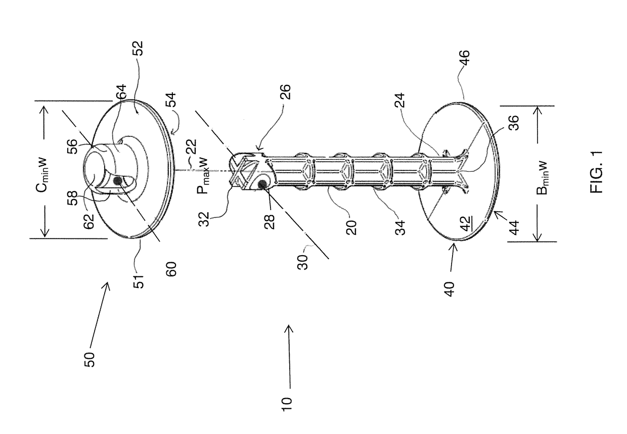
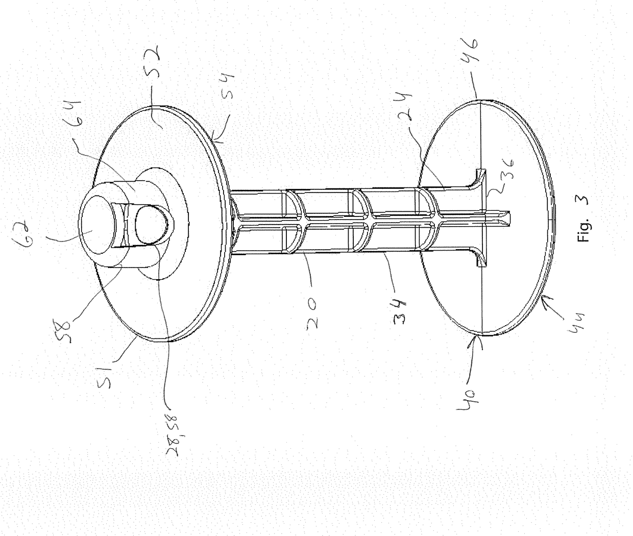
[0040]As with the other embodiment, bottom 136 of first end 24 of post 120 is preferably integrally connected to an upper surface 142 of base 140, which also includes a lower surface 144, opposite upper surface 142. Base 140 extends outwardly from the bottom 136 of each post 120 forming a rim 146. As with the first embodiment, rim 146 of base 140 has a minimum width, Bminw, that is greater than a maximum width, Pmaxw, of the post140, measured in a direction perpendicular to the central axis 122. The design of the rim depends on factors such as the number of posts present and connected to base 140, size of the body, composition of the body and constructions in which the foreign material exclusion device will be utilized. The height of each post can vary as described hereinabove. That said, in various embodiments, the Bminw is greater than or equal to 1.25 times the Pmaxw, or greater than or equal to 1.5 times the Pmaxw or even greater than or equal to 2 times the Pmaxw.

[0041]Cap 150,...


PUM


Abstract

A retaining member particularly suitable for use as part of a foreign material exclusion device that can be used to temporarily seal an area of a construction from foreign material or debris, wherein the retaining member includes a post adapted to be inserted through a body of the foreign material exclusion device and cap having a rim and a fitting, the latter mateably engageable with an end of the post. The post and fitting each include through bores that are alignable such that they can be connected, for example with an extraction member of the foreign exclusion material device. Foreign material exclusion devices including the retaining member are disclosed.

Description

FIELD OF THE INVENTION[0001]The present invention relates to a retaining member particularly suitable for use as part of a foreign material exclusion device that can be used to temporarily seal an area of a construction from foreign material or debris, wherein the retaining member includes a post adapted to be inserted through a body of the foreign material exclusion device and cap having a rim and a fitting, the latter mateably engageable with an end of the post. The post and fitting each include through bores that are alignable such that they can be connected, for example with an extraction member of the foreign exclusion material device. Foreign material exclusion devices including the retaining member are disclosed.BACKGROUND OF THE INVENTION[0002]During assembly or maintenance of various assemblies or constructions in various industries, it is desirable to prevent the introduction of debris into one or more areas to prevent damage to various objects or prevent safety hazards. F...

Claims


Application Information

Patent Timeline
IPC IPC(8): F16L55/11
CPCF16L55/11F02C7/00F05D2230/00F16L55/1141F16L57/005
Inventor NOLFI, THOMAS J.NOLFI, MARIO M.
Owner ADVANCED F M E PROD
Features
  • R&D
  • Intellectual Property
  • Life Sciences
  • Materials
  • Tech Scout
  • Unparalleled Data Quality
  • Higher Quality Content
  • 60% Fewer Hallucinations
Learn More