Vehicle Storage and Charging Station

Active Publication Date: 2018-12-27
THE UNITED STATES OF AMERICA AS REPRESENTED BY THE SECRETARY OF THE NAVY
View PDF0 Cites 30 Cited by
  • Summary
  • Abstract
  • Description
  • Claims
  • Application Information

AI Technical Summary

Benefits of technology

[0003]Described herein is a vehicle charging station comprising a container and a resource control unit (RCU). The container comprises upper and lower portions. The upper portion has an air duct and is configured to mate with the lower portion to form a weather-tight enclosure around a vehicle. The lower portion comprises a support structure, a smoke detector, a fire-suppressant inlet, and a charging/communications junction. Removal of the upper portion allows for loading/unloading of the vehicle into/out of the lower portion. The RCU comprises a processor, an environmental control unit (ECU), a fire-suppressant control manifold, and a charger. The ECU is operatively coupled to the air duct. The fire-suppressant control manifold is operatively coupled to the fire-suppressant inlet. The charger is electrically coupled to the charging/communications junction. The processor is communicatively coupled to the smoke detector, the charging/communications junction, the ECU, the charger, and the fire-suppressant control manifold.
[0004]An embodiment of the vehicle charging station may be described as comprising a container, a support structure, an air duct, a smoke detector, a charging/communications junction, a fire-suppressant inlet, and an RCU. The container has an upper portion and a lower portion where the upper portion is configured to mate with the lower portion to form a weather-tight enclosure around a vehicle. Removal of the upper portion allows for loading/unloading of the vehicle into/out of the lower portion. The support structure, which is configured to inhibit movement of the vehicle in three dimensions with respect to the su

Problems solved by technology

Current charging/storage stations for vehicles can be bulky, and difficult to work with.
Moving the UUV in/out of the MILVAN container can require a significant amount

Method used


Image

  • Vehicle Storage and Charging Station
  • Vehicle Storage and Charging Station
  • Vehicle Storage and Charging Station

Examples


Embodiment Construction

[0016]The disclosed methods and systems below may be described generally, as well as in terms of specific examples and / or specific embodiments. For instances where references are made to detailed examples and / or embodiments, it should be appreciated that any of the underlying principles described are not to be limited to a single embodiment, but may be expanded for use with any of the other methods and systems described herein as will be understood by one of ordinary skill in the art unless otherwise stated specifically.

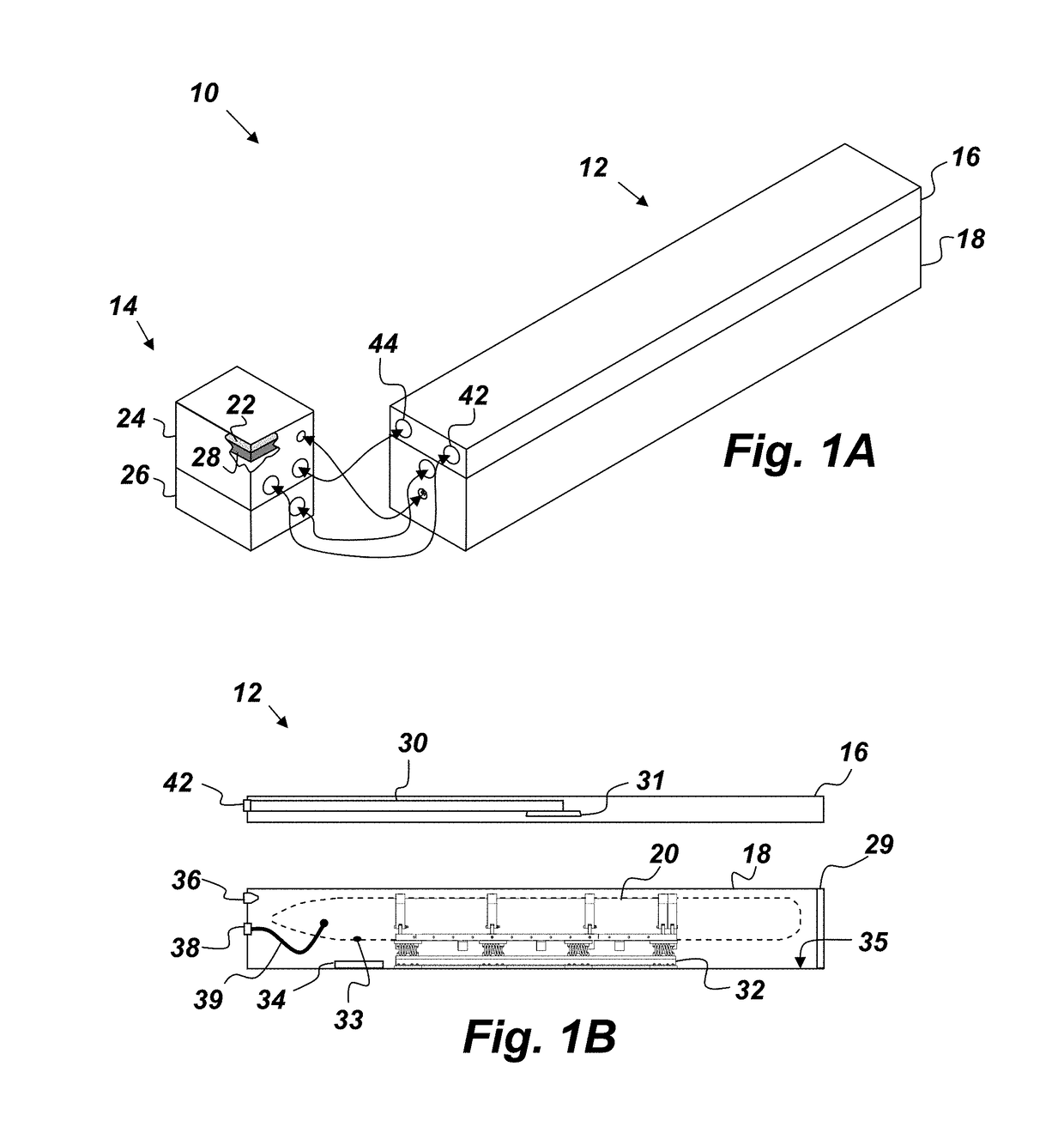
[0017]FIG. 1A is a perspective view of an embodiment of a vehicle charging station 10 that comprises, consists of, or consists essentially of a container 12 and a resource control unit (RCU) 14. The container 12 comprises an upper portion 16 and a lower portion 18. The upper portion 16 is configured to mate with the lower portion 18 to form a weather-tight enclosure around a vehicle 20 (such as is depicted in FIG. 1B). The vehicle charging station 10 provides a safe ...


PUM


Abstract

A vehicle charging station comprising: a container comprising an upper portion having an air duct, and a lower portion comprising a support structure, a smoke detector, a fire-suppressant inlet, and a charging/communications junction, wherein the upper portion is configured to mate with the lower portion to form a weather-tight enclosure around a vehicle, and wherein removal of the upper portion allows for loading/unloading of the vehicle into/out of the lower portion; and a resource control unit (RCU) comprising a processor, an environmental control unit (ECU), a fire-suppressant control manifold, and a charger, wherein the ECU is operatively coupled to the air duct, the fire-suppressant control manifold is operatively coupled to the fire-suppressant inlet, the charger is electrically coupled to the charging/communications junction, and the processor is communicatively coupled to the smoke detector, the charging/communications junction, the ECU, the charger, and the fire-suppressant control manifold.

Description

FEDERALLY-SPONSORED RESEARCH AND DEVELOPMENT[0001]The United States Government has ownership rights in this invention. Licensing and technical inquiries may be directed to the Office of Research and Technical Applications, Space and Naval Warfare Systems Center, Pacific, Code 72120, San Diego, Calif., 92152; voice (619) 553-5118; ssc_pac_t2@navy.mil. Reference Navy Case Number 106063.BACKGROUND OF THE INVENTION[0002]The invention described and claimed herein relates to the field of vehicle storage and charging stations. Current charging / storage stations for vehicles can be bulky, and difficult to work with. For example, many unmanned underwater vehicles (UUVs), such as the MK 18 Mod 2 Kingfish, are transported and stored in an approximately 6×2.5×2.5 meter (20×8×8 feet) steel container, or MILVAN. Moving a MILVAN container requires a forklift or crane capable of lifting 9072-11340 kg (20-25K pounds). Moving the UUV in / out of the MILVAN container can require a significant amount of f...

Claims


Application Information

Patent Timeline
IPC IPC(8): B60L11/18A62C3/16A62C37/40B65G1/02H02J7/00
CPCB60L11/1824A62C3/16A62C37/40A62C3/10H02J7/0042B60L2200/32B65G1/02A62C37/04B60L2250/10B60L53/302B60L53/305B60L53/31Y02T10/70Y02T10/7072Y02T90/12Y02T90/16B60L53/30
Inventor HOOPER, RALPH DAVIDGILCHRIST, JEFFERY TOWNSCHAMBERS, WILLIAM A.EASTERWOOD, BRADLEY JOSEPHLASSUS, BRETT PAULCOLLINS, PAUL MICHAELEDWARDS, SAMUEL THOMASSILAS, TERRY LANCEROTH, MARC LUDWIGBARKER, HARRY LYNNBENNETT, STEVEN DUSTIN
Owner THE UNITED STATES OF AMERICA AS REPRESENTED BY THE SECRETARY OF THE NAVY
Why Eureka
Try Eureka