Blast furnace stockhouse arrangement

a technology of metallurgical furnace and stockhouse, which is applied in the direction of furnaces, lighting and heating apparatus, charge manipulation, etc., can solve the problems of complex modern, automated stockhouses, etc., and achieve the effects of reducing the segregation and degradation effect of materials, improving the relative permeability of materials inside, and improving the control of material granulometry

Active Publication Date: 2018-12-27
PAUL WURTH SA
View PDF0 Cites 1 Cited by
  • Summary
  • Abstract
  • Description
  • Claims
  • Application Information

AI Technical Summary

Benefits of technology

[0023]It shall be appreciated that these measures provide a synergetic contribution that alleviates material segregation and degradation effects. Screened and sized material is readily available in the storage bins, the storage bins and weighing hoppers being designed to avoid material degradation.
[0024]The inventive stockhouse hence permits a better control of the material granulometry. This allows blast furnace operators to have a better control on the relative permeability of the material inside a batch once it is discharged inside the furnace (in addition to the ability of controlling the BF charge distribution via the top charging device).
[0025]Furthermore, avoiding material free fall into bins and weighing hoppers with consequent grain size degradation and fines generation in accordance with the present invention, leads to more compact designs of stockhouses, leading to substantial savings in terms of number of machines required, time for batch preparation and de-dusting capacity.
[0026]Also to be noted is the possibility of retrofitting. Existing installations can be modified without difficulties to conform to the present stockhouse arrangement.
[0027]The proposed stockhouse configuration leads up to a significant reduction in investment costs, through the reduction of number of vibroscreens and of steel structure weights.
[0028]In comparison with the existing systems installed in some blast furnace stockhouses, the proposed system is more flexible and adaptable, and developed to facilitate maintenance thereof.

Problems solved by technology

In practice, a modern, automated stockhouse can be quite complex.

Method used


Image

  • Blast furnace stockhouse arrangement
  • Blast furnace stockhouse arrangement
  • Blast furnace stockhouse arrangement

Examples


Embodiment Construction

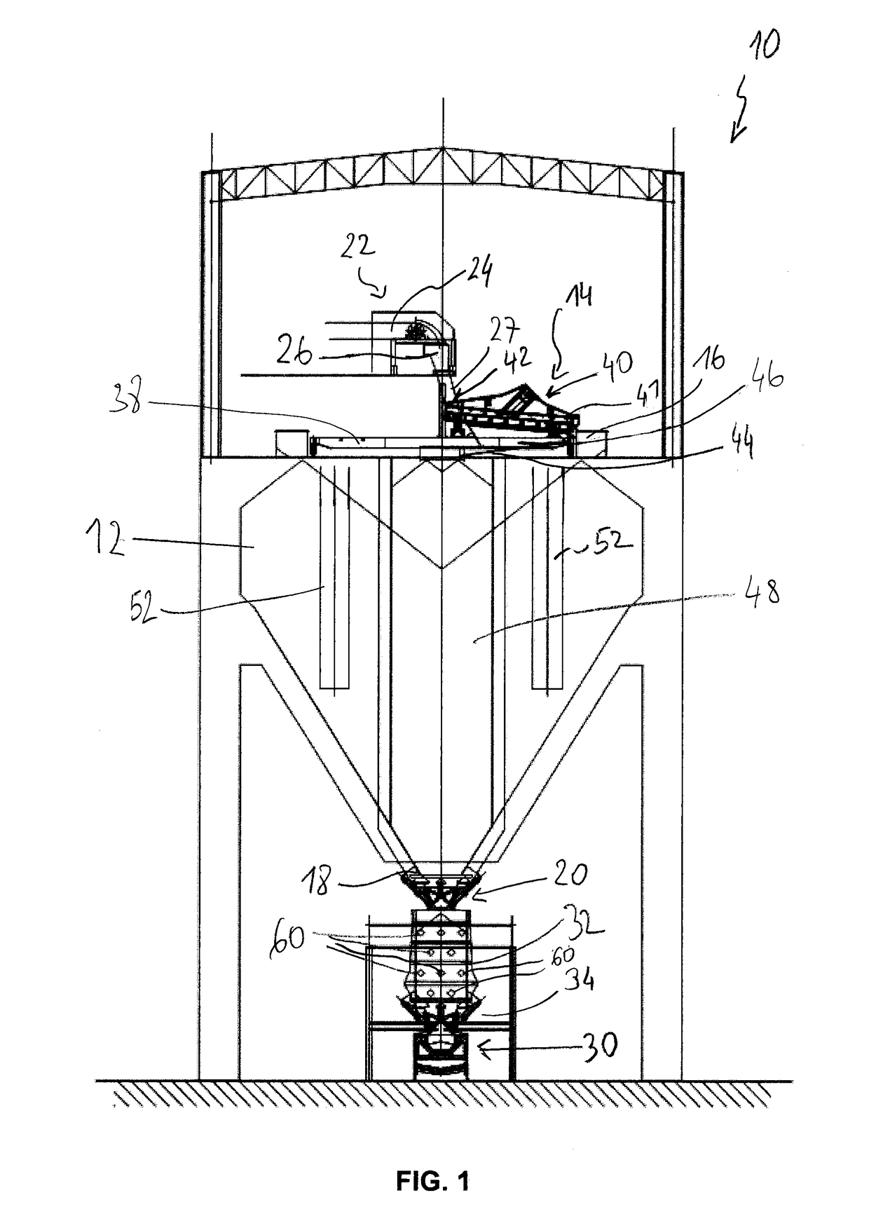
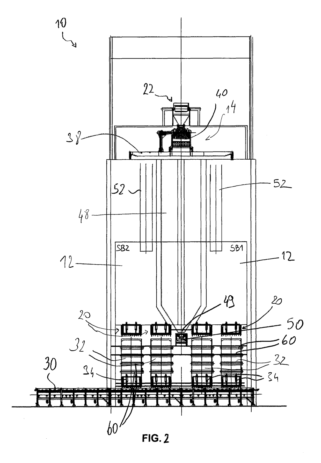
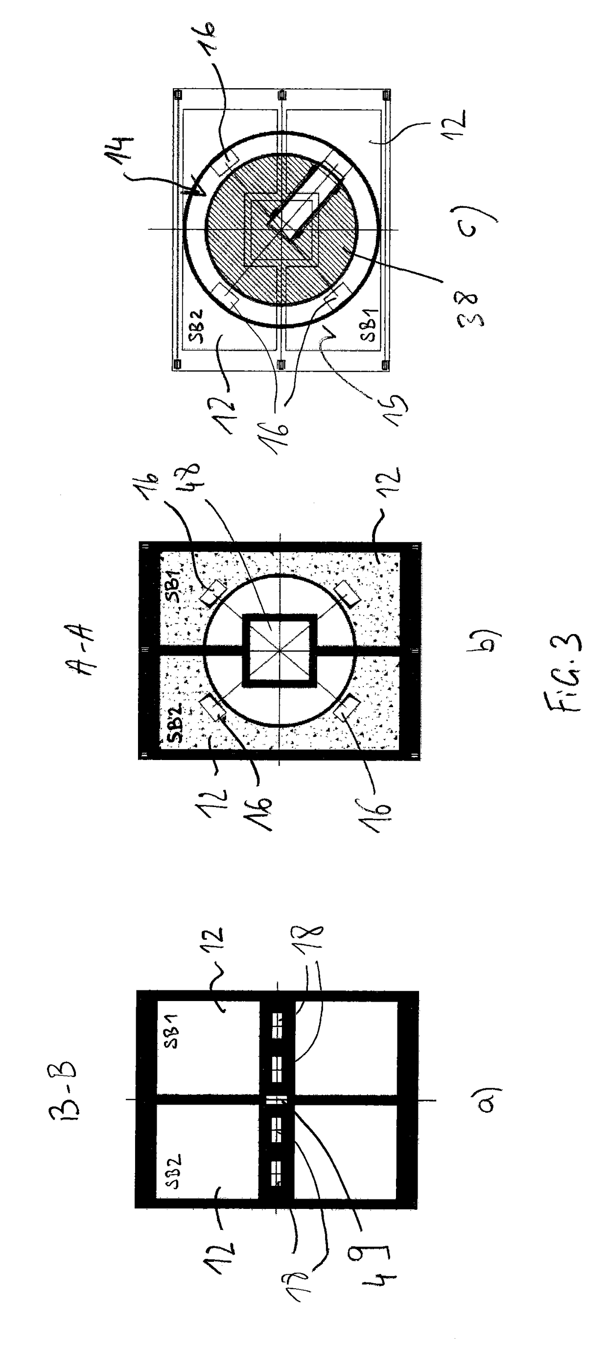
[0039]FIGS. 1 to 3 illustrate an embodiment of the present stockhouse arrangement 10 for storing, measuring and preparing charge material for a metallurgical furnace, and in particular for a blast furnace plant.

[0040]The blast furnace area with such material storage arrangement is generally referred to as stockhouse; the terms “stockhouse”, “stockhouse arrangement”, “stockhouse system” and “material storage arrangement” will be used hereinafter indifferently.

[0041]The stockhouse 10 comprises a set of storage bins 12 that are arranged in a side-by-side manner to be filled by a material feeding device 14 associated therewith. The storage bins 12 have a general hopper-like form converging towards the lower ends thereof. The storage bins 12 have a large capacity, which is typically above 200 m3, e.g. between 300 and 600 m3, and even between 500 and 1000 m3. The storage bins 12 are closed at their top by a cover 15, in which a feeding opening 16 is arranged; and have a narrow outlet 18 a...


PUM

PropertyMeasurementUnit
sizeaaaaaaaaaa
mesh sizeaaaaaaaaaa
areaaaaaaaaaaa

Abstract

A stockhouse arrangement for a metallurgical furnace includes a set of storage bins for granular material; a material feeding device associated with the set of storage bins, the material feeding device being arranged above the set of storage bins and allowing to selectively fill each of the storage bins with granular material; and a raw material feed system to convey raw granular material to the material feeding device, wherein a respective weighing hopper is arranged downstream of each storage bin and including an outlet associated with a feeding gate. A and a charge conveying system is provided for collecting and conveying material selectively discharged from the weighing hoppers through their respective feeding gate, the material feeding device being configured to screen raw granular material arriving from the raw material feed system such that only material with desired granulometry is forwarded to the respective bin(s).

Description

FIELD OF THE INVENTION[0001]The present invention generally relates to the field of iron making equipment and more specifically to a stockhouse arrangement for a metallurgical furnace, in particular a blast furnace.BACKGROUND OF THE INVENTION[0002]As it is well known, the blast furnace charging system consists of two main areas, the stockhouse system and the top charging equipment. The function of the stockhouse system is the weighing, batching and delivering of the recipe of raw materials to the top charging equipment, which is installed above the blast furnace. The top charging equipment, in turn, serves the function of delivering blast furnace raw materials to the furnace top and distributing these materials into the furnace.[0003]The stockhouse comprises a set of storage bins that are usually fed by a feed system with conveyor belt. The raw materials are drawn from the storage bins by vibrating feeders and screens into weighing hoppers, optionally via belt conveyors. The weighin...

Claims


Application Information

Patent Timeline
Patent Type & Authority Applications(United States)
IPC IPC(8): C21B7/20F27B1/20F27D3/10
CPCC21B7/20F27B1/20F27D3/10C21B5/008B07B13/14
Inventor PONGIGLIONE, GIOVANNICASTELLANI, ALDO
Owner PAUL WURTH SA
Why Eureka
Try Eureka